
Digital Volt Meters
This is a very basic “how to” use a multimeter to check circuits. A digital multimeter is a very cheap (can find them for under $15) and useful tool to have in your toolbox. A test light is cheaper, but it won’t give you as much information, Test lights usually only indicate Voltage only. Even with the cheap meters you can still manage to get enough data to figure out what is happening with a circuit in your vehicle.
Some basic things you need to know.
1) Ohm’s Law: V = I x R
* V= Voltage (volts, we work with 12 volt systems)
* I= Current (Amps, amp draw)
* R= Resistance (the resistance, or voltage/current loss in a circuit)
Why is this important?
If you can get two out of the three, you can figure out the third by simply manipulating the data. V = I x R can be manipulated to find Resistance easily. R = V / I and can be manipulated to find Current I = V / R.
2) Be VERY careful when working around power sources:
A current blast as little as .5 Amps can throw off the rhythm of your heart, it won’t affect you right away, but it gets very painful, and can kill you.
While it’s uncommon to be electrocuted while working on a vehicle, it is VERY. VERY possible. Alternators and other components can kick out some very high voltages and amperages. So just be careful!
So let’s get started:
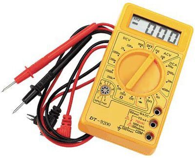
This is your basic volt meter we will be using:

For an example.
To test Voltage (V) and resistance (?) (that’s the omega symbol, how resistance is measured), you are going to want to plug your Red Lead into the V ? mA slot and the Black Lead into the COM slot.
That little lightning bolt indicates that the leads are fused at this point, if you start pulling in a ton of voltage, the system fuse will pop. These specific Multimeters read up to 750 Volts, anything above that and it will blow the fuse to protect the meter.
Testing Source Voltage:
Anytime you have a component that won’t work, you’re going to want to test it’s source voltage, to ensure that you have source power. The source power in this case is the battery. This is where we will test Source Voltage.
It’s rather simple.
Set the Multimeter (as seen above) to 20 Volts DC (DC is indicated by a straight line, with a dashed or dotted line beneath it). 20 VDC doesn’t mean we have to test 20 volts, it’s “up to” 20 Volts, and is usually the application for automobiles (in most cases there are components that have an output of more than 20VDC on a vehicle, but if you know what they are, you already know how to use a multimeter)
Now, take the Red Lead and put it against the Positive post of the battery, and take the Black Lead and put it against the Negative post of the battery.
This is a diagram of testing Source Voltage:
Now when testing your battery, it’s going to read a little weird.
A battery says it’s 12 VDC. But here’s the deal, it will usually test from 11.5 VDC to 12.5 VDC depending on the age of your battery, without the motor running
With the motor running it should read 12.5 VDC to 14.5 VDC. In order to charge a battery back to 12 volts, while under a load, you have to run a little more voltage to it. If you’re reading within 2.5+ volts of 12, you’re fine, you’re not overcharging.
If you’re reading more than 15 VDC, your alternator may be overcharging your battery!
If you’re reading 12 VDC, you’re alternator isn’t charging your battery, it’s basically maintaining your battery.
If you’re reading less than 12 VDC, you’ve got an issue with your source voltage and your alternator, or battery.
Okay now that we’ve broken you in, on how to test voltage, we’re going to want to move on to something a little harder.
The nice thing about vehicles is, that the body is grounded to the frame, the frame is grounded to the battery. The Black Lead can be put to any steel surface and it’s considered a ground, you can take the Red Lead and test prior to a fuse or component, and after a fuse or component, as seen here:
Testing for voltage prior to the fuse:
Testing for voltage after a fuse:
Before and after a fuse, should read source voltage!
Lets get on to testing resistance, or ? (Ohm’s):
When testing something like a positive battery cable, it’s best to remove the battery cable from the source and the destination to test resistance. Components and sources can have a resistance of their own, that will throw off the reading of your multimeter.
So lets say you’ve removed your Positive battery cable, how do you test it for Resistance (or continuity, depending on who you are).
Back to the multimeter:
Move the dial to the symbol of a little circle with soundwaves coming off of it. For this purpose, you’re testing for Total Resistance of 0. You expect to have Zero resistance. You don’t want any Resistance between source power and the destination (like your starter).
Test your meter. Take the Black Lead and touch it to the Red Lead, the meter should now beep, and the digital reading should scroll down to 0.0000. There should be no resistance in your meter!
So you’ve got the multimeter set right. Take the Black Lead, place it on one end of the cable, take the Red Lead, and place it on the other end of the cable.
When testing for resistance (0?), polarity doesn’t make a difference. Resistance doesn’t travel in any direction, it’s just testing to ensure the path is clear.
The meter should now start to squeal. If it doesn’t squeal, you have resistance in the positive battery cable. Resistance in battery cables will cause problems, the path is not clear, the voltage and current is constricted when traveling and it’s not all making it to the component.
Testing resistance in your wiring through out your vehicle is pretty much the same concept.
You cannot test the resistance of a component and get a clear indication of what it means. Different components (like a blower motor) are going to have different resistance, depending on the component. What you can do is read the resistance in the wire to and from the component.
Do not try to read resistance from the (+) positive side of component, to ground (-). Test after the component, to ground. The component will give you a faulty reading.
When testing a fuse, remove it from the holder and test it as a single entity. A fuse should make your meter squeal and the digital reading should be 0.0000. The reason you want to test a fuse as a separate entity is because a fuse can actually blow, and re-solder itself shut. This will create resistance, removing it from the holder gives you the ability to physically look at the fuse. If it looks like it soldered itself shut again, replace the fuse! They’re CHEAP!
If you test a conductor, like copper wire or a fuse:
And your meter doesn’t do anything, doesn’t squeal, the digital display doesn’t move, you have an open in your wiring. The reading is called an “infinite” reading, ? is infinite, total resistance, current and voltage will not travel through infinite ?. This means that the fuse is blown, or somewhere between point A and point B, the wire is broken or not connected. At this point, trace the wiring back to find the open.
If you test a conductor, to ground, prior to the component:
And your meter squeals and the digital meter indicates you have a short. This means somewhere your (+) is grounding out to the body, frame, or negative wire of the circuit. With the power on, you’ll probably blow fuses if this is happening.
Testing amp draw or Current (I):
In order to test amp draw or current, you need to break open the circuit.
There really isn’t a reason to do this for the backyard mechanic. If you’re blowing fuses your drawing too much current.
But just in case you wanted to know (THIS IS FOR DC CIRCUITS ONLY):
Remove the Red Lead and place it into the 10ADC slot, turn the dial to 200 A selection.
You would have to break the circuit, and actually let the current and voltage run through your meter as so:
These:
are a very good thing to have when testing Current or Amp draw, you NEVER want to HOLD leads in place when breaking open a circuit and running current and voltage through it.
Some tips:
~When adding a new circuit, such as lights. Always, always, always FUSE the positive feed to the lights or component. It’s much cheaper to replace a fuse rather than the component completely.
~When doing something like testing your rear window switch wiring, don’t test THROUGH the switch, check the switch independently of the wiring, you can get false readings when testing multiple components and conductors.
~ALWAYS, show great caution and appreciation for electricity of any sort. The instant you start taking it for granted is when it will bite you.
~DON’T be a ground. Wear rubber soled shoes and don’t touch one hand to the positive end of a circuit and touch steel with the other hand, you become insta-ground, and like i said earlier, something as little as .5 Amps can throw off the rhythm of your heart, it may not kill you, but it will mess you up for a little while.
~NOT ALL MULTIMETERS are the same, some of them have different limitations and settings, this is a basic multimeter use thread.
Once again and in conclusion:
This is a VERY basic tutorial on how to use a multimeter when testing your truck. Some of this is my opinion, not everyone may do it this way, it’s the way i do it. If you see any blatant mistakes, please let me know so i can correct them. I’ve been up a little too long.
A Multimeter and a test light are two very important tools that you can use to make sure that your electrical system is running properly.