If this is your first visit, be sure to
check out the FAQ by clicking the
link above. You may have to register
before you can post: click the register link above to proceed. To start viewing messages,
select the forum that you want to visit from the selection below.
Please let us know if things are working or not. This is still somewhat a work in progress so don't be too surprised if things magically appear from one visit to the next.
I really think something in the coloring used on the wire insulation determines how fast the wires break down. When I rewired my 1939 Philco, some of the wires were fine, some were shot. All the red were done for, most of the green were bad, but almost all of the black were fine. Other colors were hit and miss depending on location.
more wiring goodness - I finally bandaged the cracked wires behind that fender connector... I un-taped the harness back enough to get behind all the cracks and shrink wrapped them. Only each of the red wires were cracked :confused:
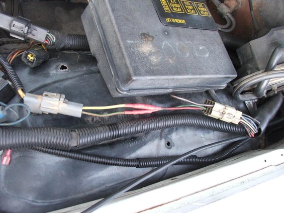
You can see here (split loom is off for the pic) how and where I joined the 3G wiring into the car's wiring.
The yellow 'sense' wire on the 3G harness is wired into the red/green 'run' wire, and the green one is wired into the green/red wire for the excite trigger and warning light.
Since the coil wiring has been previously changed, this is the only connection I have remaining here, aside from the bridge the brown wire makes.
Everyone else will need to keep the coil wiring of course, but the wiring between the old alternator and the regulator can go.
Along with the alternator/coil/regulator wires, this connector also holds the wires for the oil level, pressure, and temperature sensors (which have also been removed). This should be the same for most 85 and older cars...
yes if you have some!!
I need the magical (7" I think) 5.0 explorer TB/spacer bolts... Mark said these are what he used to hold his upper/spacer down. The stock ones are too short since I am using a spacer, and the ones you see are the next longest ones I could find between 4 stores!!!
The heater hose fittings are just a 1/2" 90 degree pipe elbow and a bling bling heater hose fitting I found at auto zone.
The hoses are different because the CFI outlet wouldn't work with the SEFI upper, and I dont like the silly pipes bolted to the intake. I had intended to have it point more towards the rear, but the fuel line was in the way. The ECT sensor is now back in the unused water port under the upper intake. I eventually plan to find a molded 3/4" hose with an elbow bend in it to get rid of the ghetto plastic elbow deal
Finally got around to dropping a 3G in... I sure do love the easy mods!
I used a small case 3G, and it fit my 65 amp external regulated alt brackets with no cutting or grinding. Getting the belt on was a little tricky, since the 3G pulley seems a tad wider, and the bulkier case of the 3G limited the tension travel to the last half of the adjustment notch.
I just used the longer 505 belt and loosened the alternator brackets up, this gave me just enough wiggle room to pop the belt over the pulley.
I used an OEM 3G charge wire I found in an early 90's Explorer - this one has two fuse links in the wire and was just the right length to reach my fuse box. It looks like if you dont tuck it away, it may reach the + terminal of a top post battery...
I wired it to 'sense' off the output stud temporarily until I work some mojo on the fender end of the old wire harness to splice this and the excite/warning lamp wires in. A few of the wires behind the car-end of the connector are cracked up... I want to pull each one out of the connector and put some shrink tubing on them...
I also learned that the warning lamp circuit IS the excite signal for the thing to charge... I knew the green wire was for the lamp circuit, but I didn't know it was needed to charge. When i started it up it didn't charge until I made a quick-jump for the warning lamp circuit...
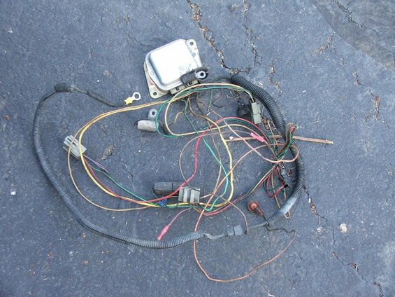
wiring I removed (this is also the old coil wiring... its unused since the SEFI conversion eliminated it and it shares the alternator harness)
I also installed the vacuum box/relay holder Tom brought me... the one and a half studs worked great mang!!


") Are they from the car's CFI days mang?
Are they from the car's CFI days mang?

Leave a comment: