
Rotary HVAC control swap into a 1993 Ford Crown Victoria
First… the obvious… remove the old HVAC controls.
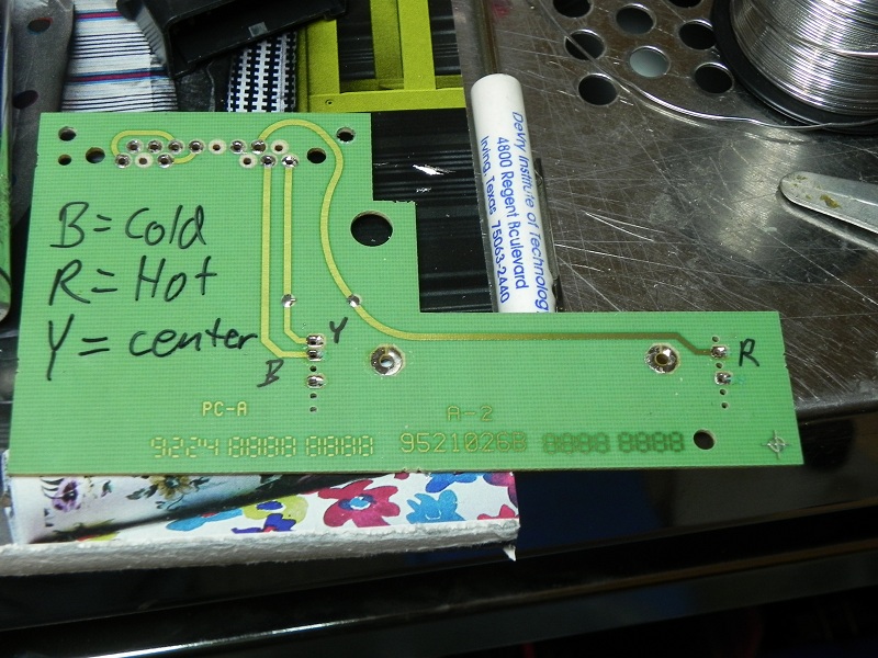
Remove the “Black Box” from the top that has the electrical slider in it. You’ll need the connector off the board. Note the traces on the left of the connector header (I’ve already removed the connector). This tells you which lines to jumper together. I’ve also noted on the board which wires from the new connector to the rotary temp control go. (B=Blue, R=Red, Y=Yellow… Cold and Hot are reference to when each line hits zero ohms)
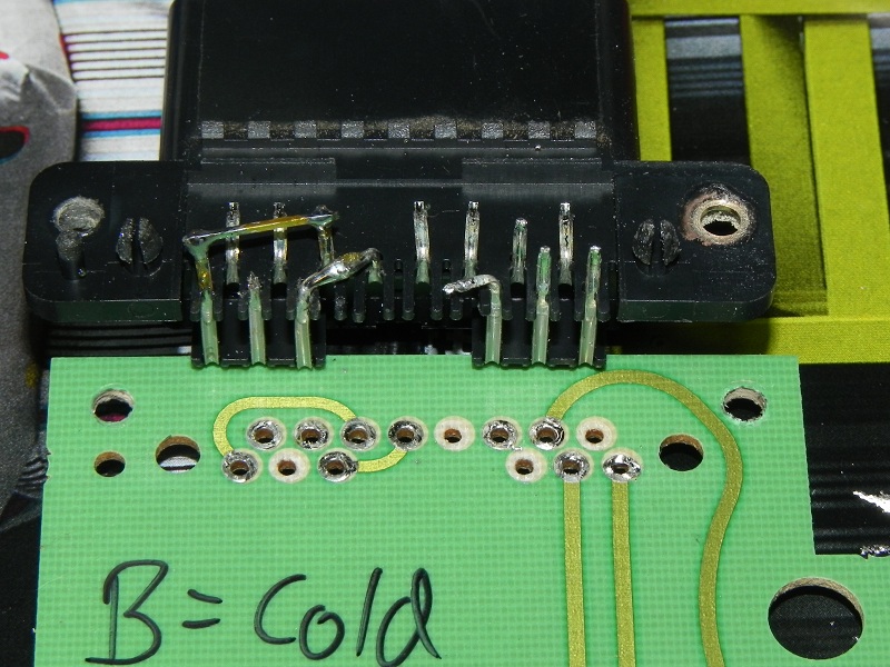
You will need to drill out the rivets that hold the connector at each end. A de-soldering tool will help immensely here as a soldering wick might not be able to get it all out of the hole.
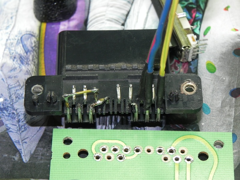
Then wrap with electrical tape for that no more shorts feeling…
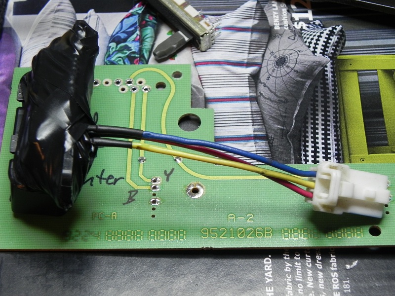
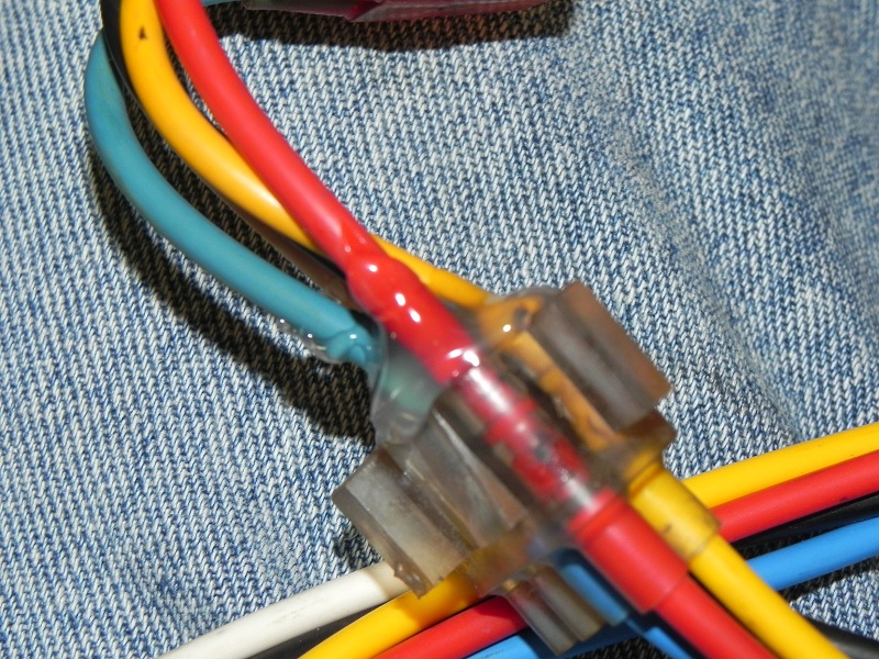
This plugs into the large connector for the stock manual controls and adapts that to the little 3-wire connector for the new controls.
Next, we re-pin…
Match color for color on the fan control. A small flat screwdriver works wonders for getting the tabs to release the pins from the connector (no soldering required).
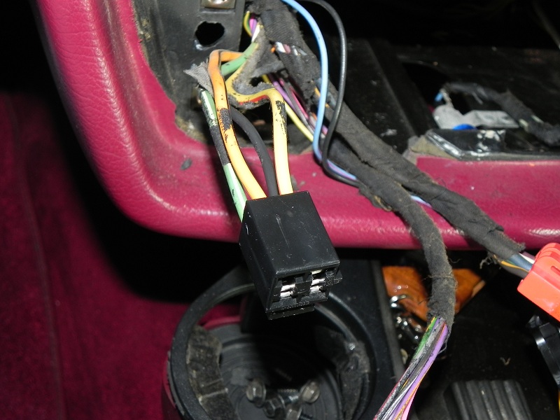
The original order is A B C D. The new order is C B D A.
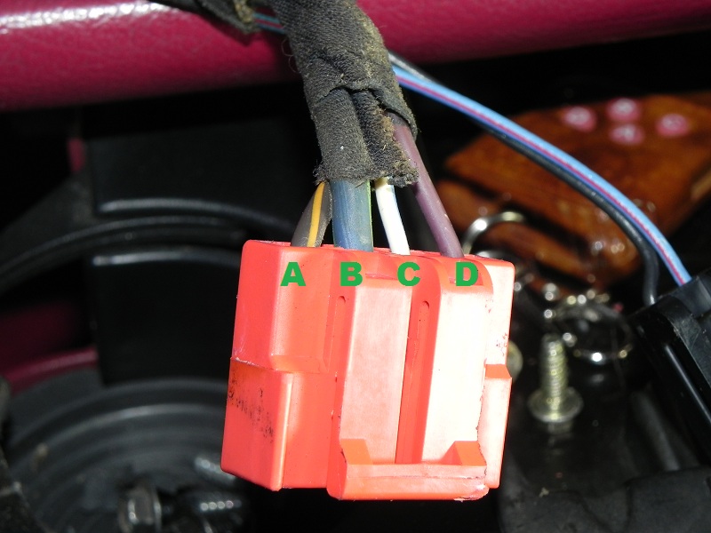
Match the vacuum connections color for color as well…
I secured the two segments together with hot glue since I have it on hand.
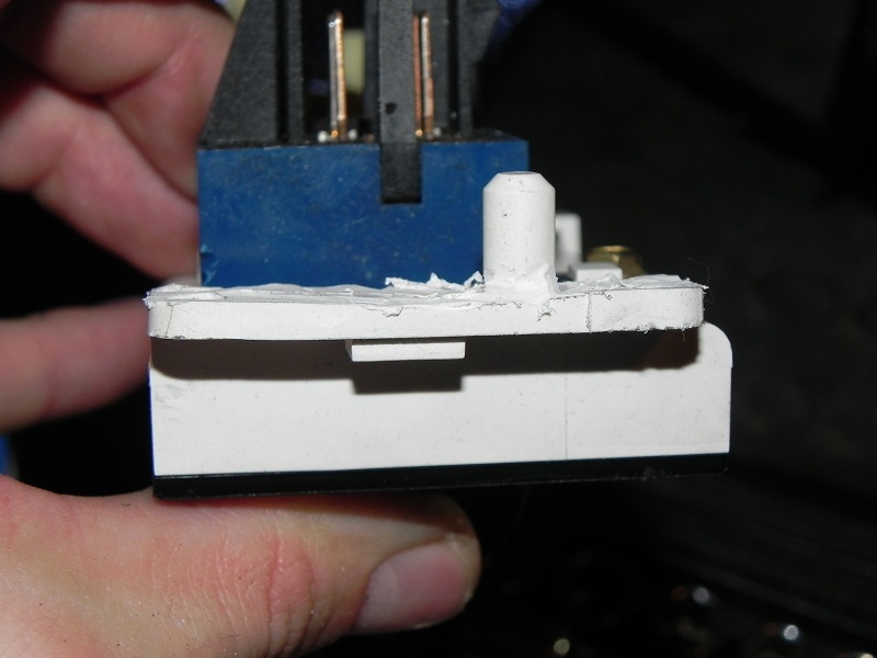
You will need to thin down the mounting ears of the controls so that they will fit. (Actually going about 1/8 inch more would have been perfect… but that’s a little too thin for my liking. I just took out the raised edge so that the plastic was totally flat.)
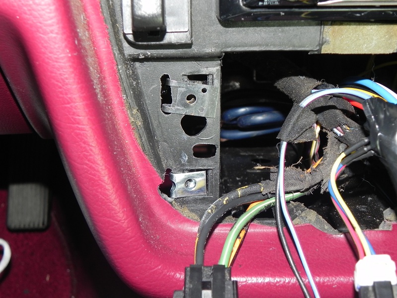
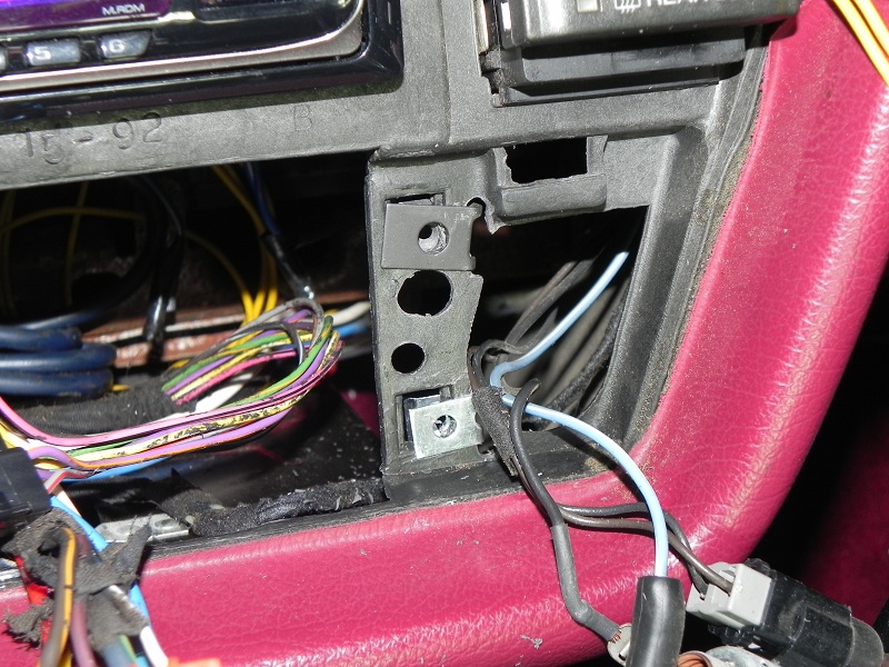
Now, the dash mods. You’ll have to remove the stock clips and edge out the square holes to clear the width of the controls. You’ll need to drill new holes for the pegs as well. You will also need some speed clips to replace the stock clips. I used my Dremel for most of this and a 1/4 inch drill bit on my drill for the peg holes.
Lastly, plug everything in and button it back up.
First… the obvious… remove the old HVAC controls.
Remove the “Black Box” from the top that has the electrical slider in it. You’ll need the connector off the board. Note the traces on the left of the connector header (I’ve already removed the connector). This tells you which lines to jumper together. I’ve also noted on the board which wires from the new connector to the rotary temp control go. (B=Blue, R=Red, Y=Yellow… Cold and Hot are reference to when each line hits zero ohms)
You will need to drill out the rivets that hold the connector at each end. A de-soldering tool will help immensely here as a soldering wick might not be able to get it all out of the hole.
Then wrap with electrical tape for that no more shorts feeling…
This plugs into the large connector for the stock manual controls and adapts that to the little 3-wire connector for the new controls.
Next, we re-pin…
Match color for color on the fan control. A small flat screwdriver works wonders for getting the tabs to release the pins from the connector (no soldering required).
The original order is A B C D. The new order is C B D A.
Match the vacuum connections color for color as well…
I secured the two segments together with hot glue since I have it on hand.
You will need to thin down the mounting ears of the controls so that they will fit. (Actually going about 1/8 inch more would have been perfect… but that’s a little too thin for my liking. I just took out the raised edge so that the plastic was totally flat.)
Now, the dash mods. You’ll have to remove the stock clips and edge out the square holes to clear the width of the controls. You’ll need to drill new holes for the pegs as well. You will also need some speed clips to replace the stock clips. I used my Dremel for most of this and a 1/4 inch drill bit on my drill for the peg holes.
Lastly, plug everything in and button it back up.
Attached Files


 I have everything I need to swap a later manual hvac control into The Scab (LS with factory manual controls) but I also have all the '97 LTC ATC stuff from The Ice Car (GS with factory ATC). Decisions, decisions (that I'm not going to get to any time soon
Comment