(This will be edited over the course of the week, because I don't have the time to do this write up in one sitting)
This write involves everything that entails installing a Perfomance Improved (PI) Intake Manifold on a Non-Performance Improved (NPI) engine.
First, this write up is aimed at the 92-95 NPI engines.
Secondly, this swap will be much easier for the 96+ crowd. Mainly, because you do not have to modify the engine harness.
To start things off, here is a list of parts you will need. All the items that are bold are REQUIRED for both 92-95 and 96+ systems.
Parts List:
- PI Intake Manifold (any PI will work; I used a FRPP unit from a 04 Mustang GT)
- PI Intake Manifold Gaskets(kit includes upper plenum gasket)
- Upper Intake Plenum
- Throttle body
- Idle Air Control (IAC) Valve
- Air Intake
- 96-97 Fuel Rail
- PI Heater Core Return Line
- PI Water Pump Inlet Nipple
- 96-97 Spark Plug Wire Bracket
- Water Pump O-ring
- IAC Gasket
- Throttle Body Gasket
- Thermostat Housing O-Ring
- 96+ Throttle Cable
- 96+ Throttle Cable Bracket with spring
- Fuel Injectors (Skinny)
- Fuel Injector O-Rings (16)
- 96+ vacuum lines. All of them.
- Save as much harware from the junkyard as possible.
Consumables:
- Blue RTV
- 1 gallon of coolant. I use the straight glycol and mix it myself. I see 50/50 as a waste of money.
- Brake cleaner
- Paper towels
- Beer
Specialty Tools:
- Fuel rail disconnect kit
- Mechanical fan removal kit- I forgot that most people have this still installed.
This will take a while. So don't plan on having your car for a solid weekend. It will not take 4 hours. It may take your less or more time depending on your mechanical ability and how much other maintenance you would like to get done while you have parts off your car.
1.
Find a suitible vehicle to do the swap!
2.
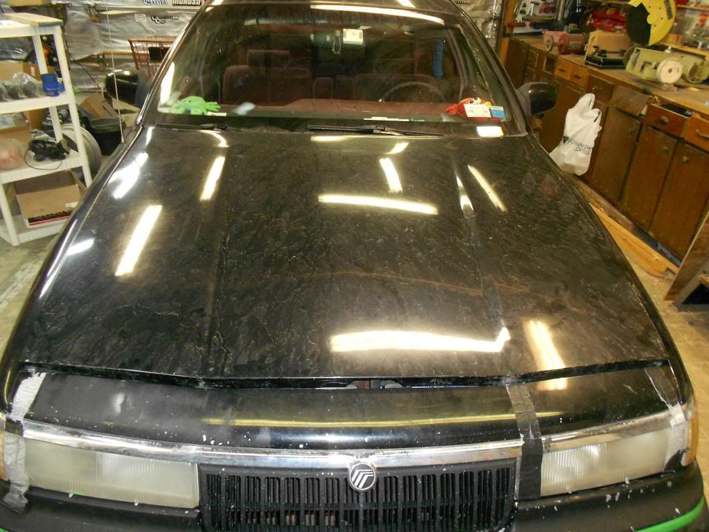
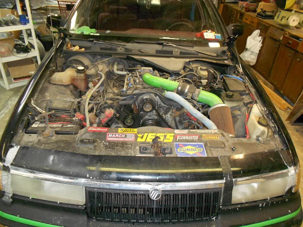
You don't have to do this, but I removed the hood for A. more light B. less hitting my head and C. more room.
3.
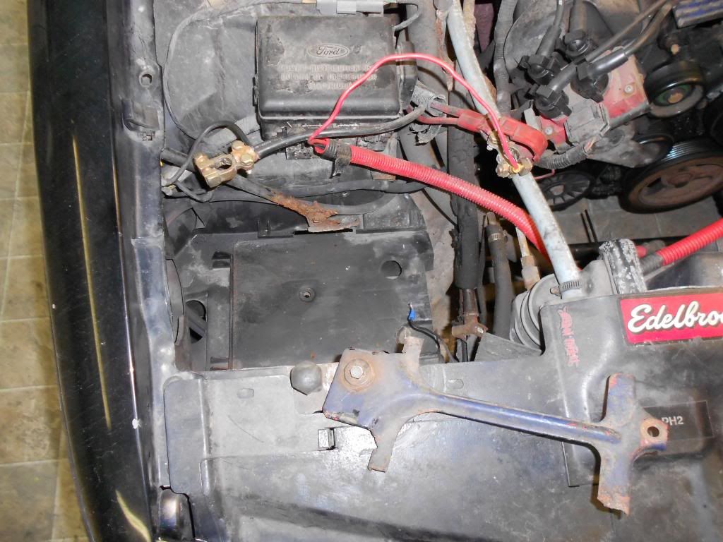
Disconnect the battery. (Another option. I removed the battery because I needed to install and new one.)
4.
Put a suitable containter under the radiator on the drivers side. Open the petcock and start to drain the coolant.
5.
Disconnect the Intake Air Temperature (IAT) Sensor and the Mass Air Flow (MAF) Sensor and remove the air intake.
6.
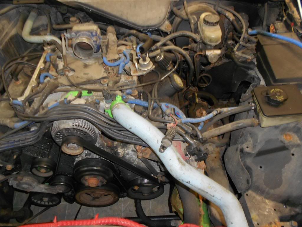
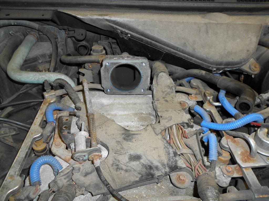
Pop off the throttle cable with a flat screwdriver, and remove the 4 8mm bolts to remove the throttle body. Set the throttle cable to side on the drivers side inner fender area.
7.
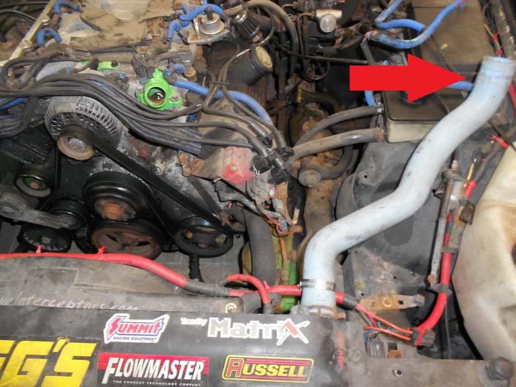
By now, there should be enough coolant drained to reposition the radiator return line. To keep the mess down, I loosened the clamp from the thermostat housing, the loosened the clamp on the radiator and rotated the hose over to the power steering reservoir. The same applies to the coolant line that goes to the heater core from the intake manifold. Disconnect it from the manifold and rotate it upwards to keep the mess down. (I remove and replaced mine with CVPI silicone hoses)
7.1
I realize that not every car has the mechanical fan removed like the Tank. Use the mechnical fan removal tool(s), loosen the fan. Remove the 4? bolts that hold in the fan shroud. Then remove the shroud and fan assembly.
8.
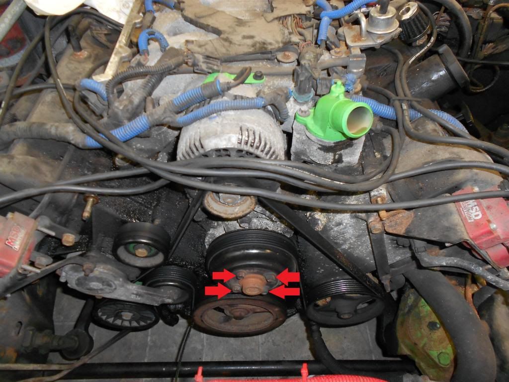
IMPORTANT!- use a ratchet or an impact ratchet and loosen the 4 10mm bolts on the water pump pulley. DO NOT REMOVE THE PULLEY UNTIL THE BELT HAS BEEN REMOVED!
9.
Disconnect all the sensors and start to remove the engine harness. On the drivers side, underneath, you do not have to disconnect the Oil Pressure Sensor or the Power Steering Pump Speed Valve Sensor. They may remained connected.
Start on the passenger side. Underneath, disconnect the Crank Position Sensor (CPS) and the Air Conditioning Clutch plug. Then, disconnect the Alternator Charge cable to the Distribution Box. Disconnect the coil pack, emissions, fuel injector wiring( 92-95- Label each injectors position. Wrap a slice of duct tape on it and write # 1-8 on each connector for it's coresponding cylinder number. The engine harness needs to be broken free of the stupid plastic piece that holds it all together on top of the intake manifold. You don't want to spend time trying to figure out which injector harness goes where), alternator wires, and coolant sensor to the harness.
9.1
-92-95 Disconnect the vacuum line to the intake plenum. then remove the braket on the backside (2 8mm bolts)<--8mm ratcheting wrench will save you]. Then remove the 4 8mm bolts and remove the intake plenum assembly.
Then make your way disconnecting everything around the back of the motor. the O2 Sensors are hooked up to the engine harness, so they may be a bit difficult to get to. Step 9.1 makes this easier for the 92-95.
Remove the connection to the IAC, Throttle Position Sensor (TPS), Exhaust Gas Recirculate (EGR) Valve and sensor. Then the drivers side fuel injectors, coil pack, camshaft sesnor, and coolant sensor. Lastly, disconnect the engine harness from the connection that goes to the Powertrain Control Mondule (PCM). It's located unter the brake master cylinder and requires the loosening of one 10mm bolt. Then carefully removed the connector and lay the entire harness on the drivers side fender/area.
Also, remove the vacuum lines as well during this time.
10.
Use a 1/2" drive breaker bar (or equivilant) and relieve pressure on the tensioner and remove the accessory belt. Replace if necessary.
11.
Remove the 3 8mm bolts and the 2 10mm bolts, then remove the alternator.
12.
By now, the coolant should be mostly drained via the petcock. Close the petcock, and move the container under the water pump. Remove the loosened 4 10mm bolts, remove the pulley, then remove the 5 13mm bolts that hold the water pump, and remove the water pump.
13.
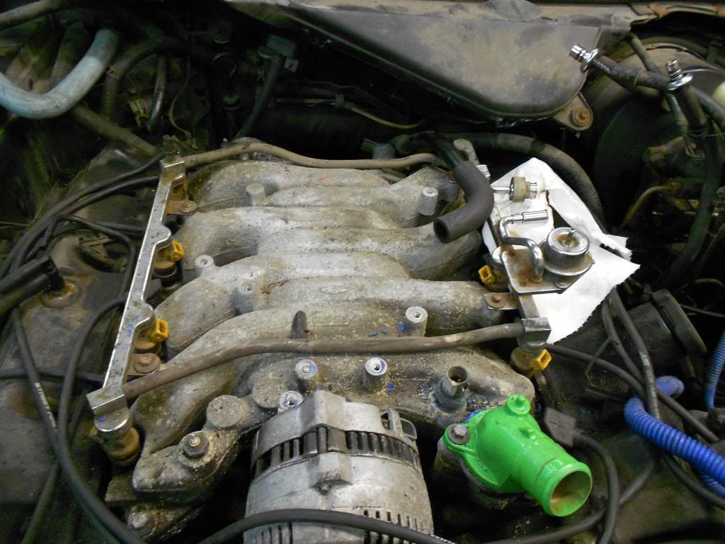
Using the fuel line disconnect tool, disconnect the two fittings that connect to the fuel rail. Take a small piece of mechanics wire/saftey wire/zip tie/string and tie the to the cap on the brake reservoir. This will keep them out of the way, and spilling gasoline and making more of a mess.
Remove the 4 8mm bolts and remove the fuel rail and the injectors.
--edit image-----
14.
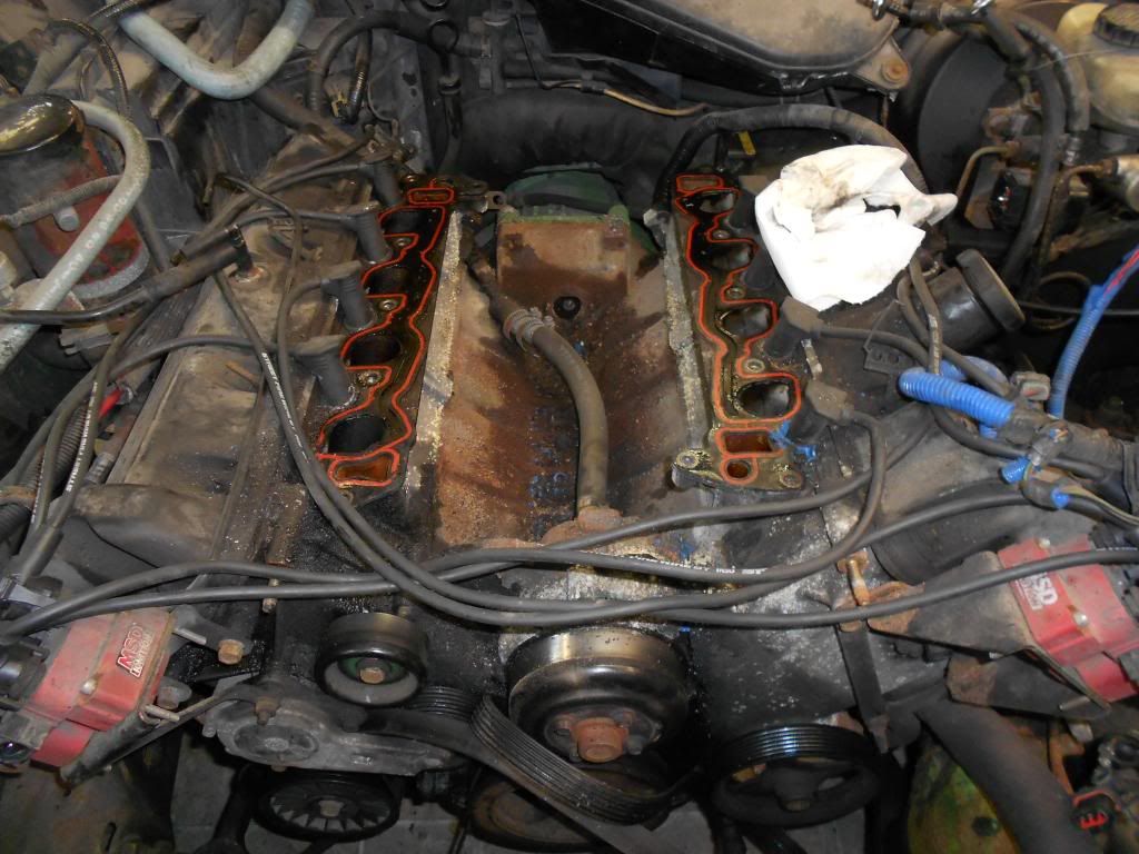
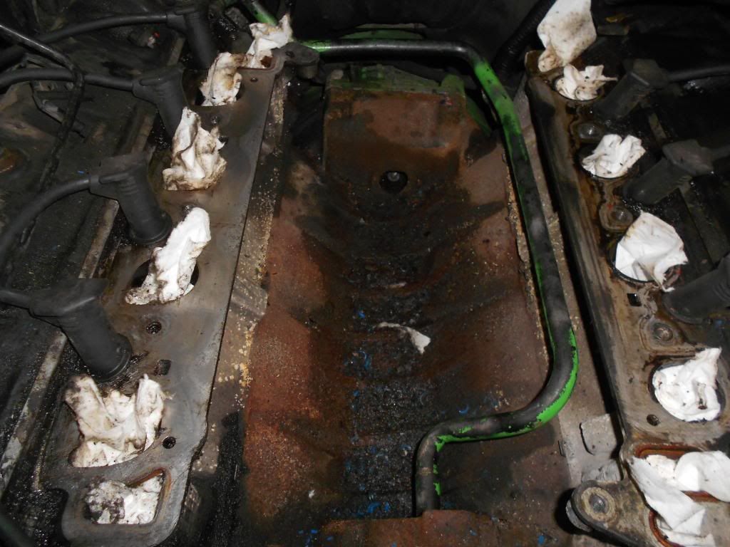
Remove the 11 10mm bolts that hold the intake to the heads. Although it is aluminum, it weighes roughly 30 lbs, so be prepared for it, especially because Panthers are so wide.
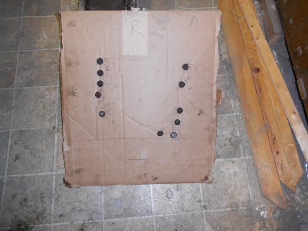
I kept the bolts in order for reinstalltion.
Intake removed:
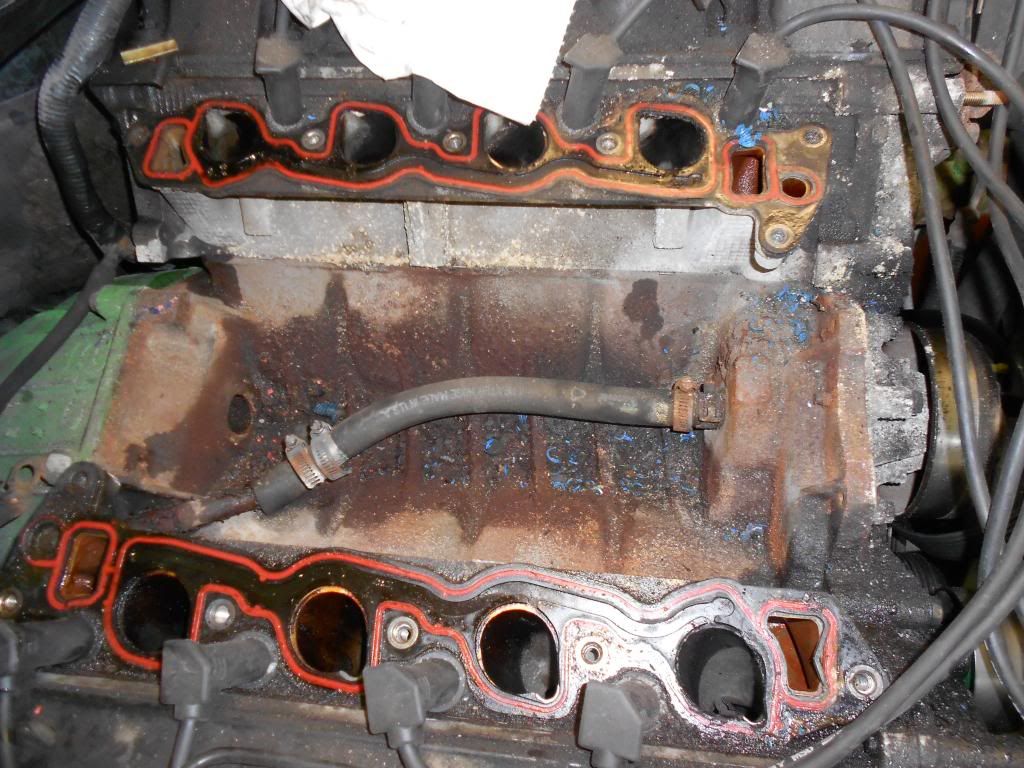
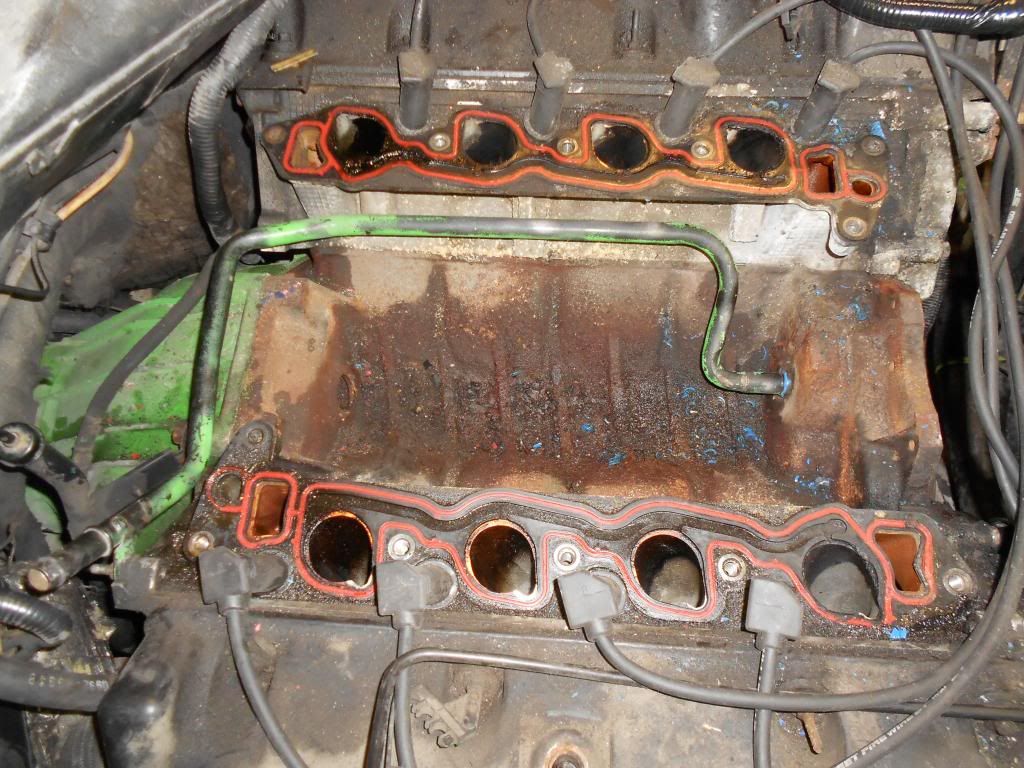
Another look, showing the Heater Core Return Line that needs to be replaced/put out of its misery.
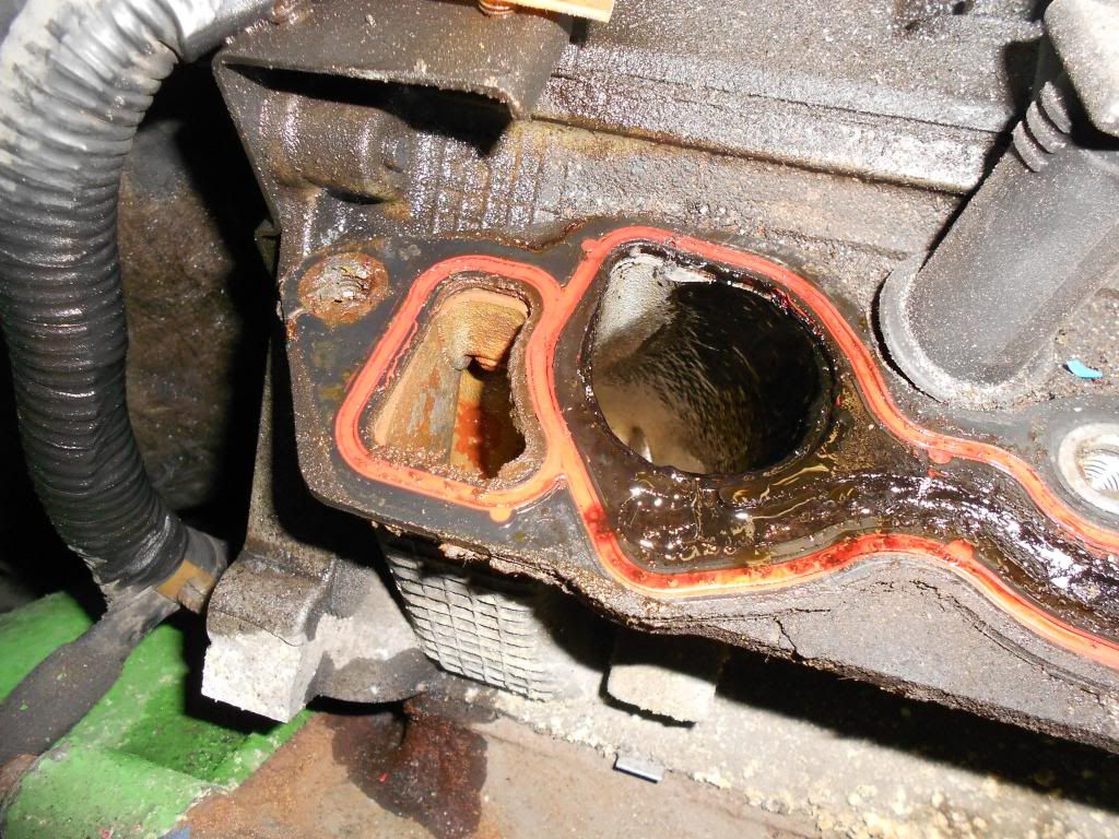
And the blown out intake manifold gasket on the drivers side. This is the whole reason this swap is going on.
15.
THIS APPLIES TO ALL VEHICLES
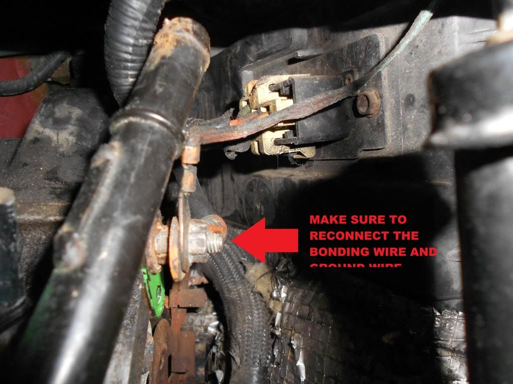
Disconnect the bonding wire from the back of the engine and remove the old Heater Core Return line.
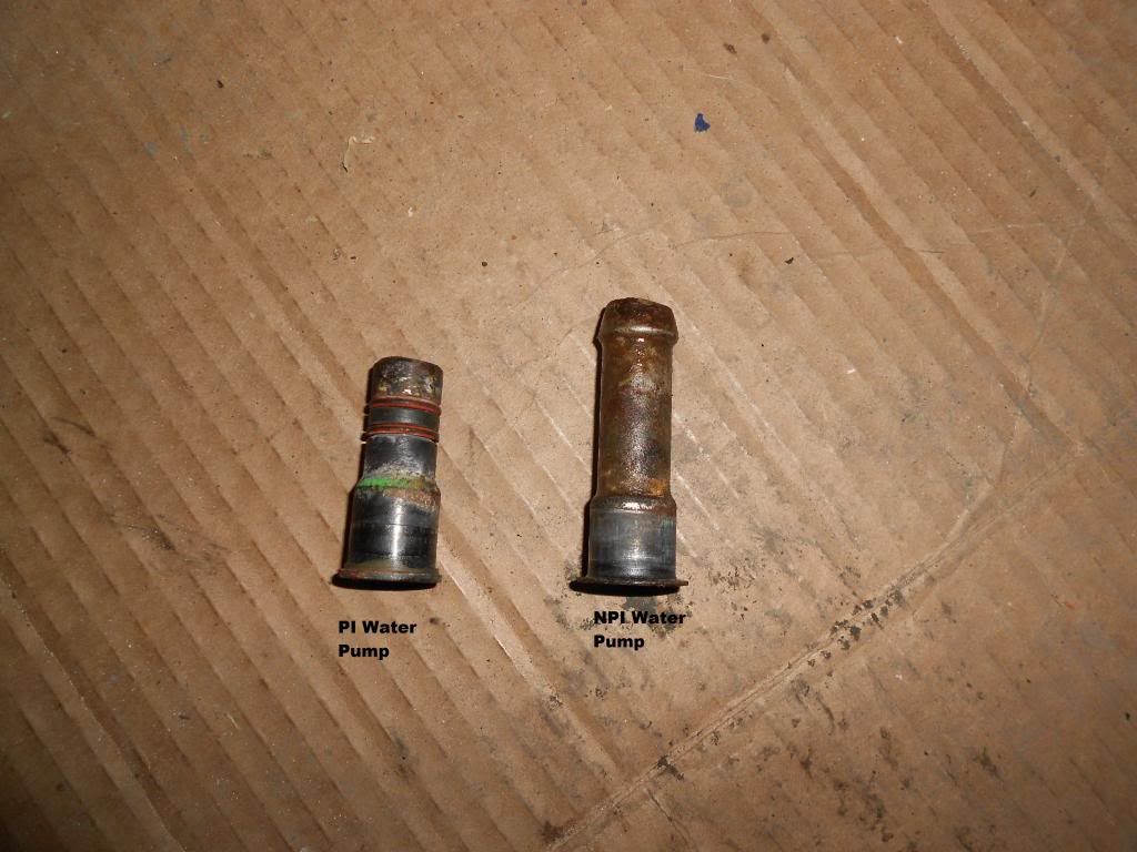
The return line has to be changed out because the PI Intake manifold is so big, that the line interferes with the manifold laying flush. The line and the nipple that it connects to on the back of the water pump must be replaced with a PI version.
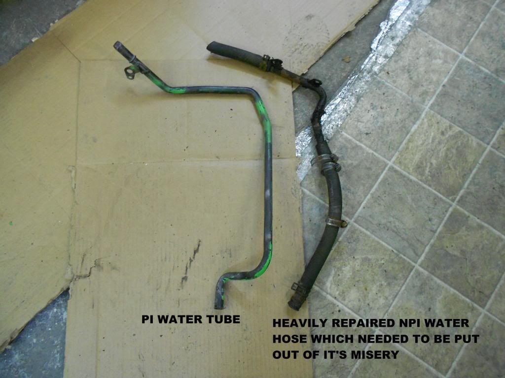
16.
Using a ball peen hammer, gently tap out the old nipple on the back the water pump.
17.
Use a deep well socket (I used an 11mm. It worked out that way) and tap the new nipple into place. I put a small amount of Blue RTV around the lip of the nipple where it mates to the block to prevent any leaking.
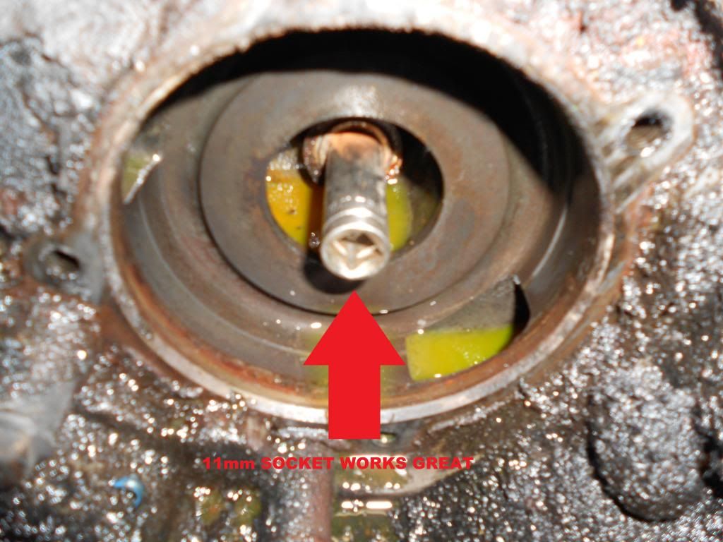
Newly installed.
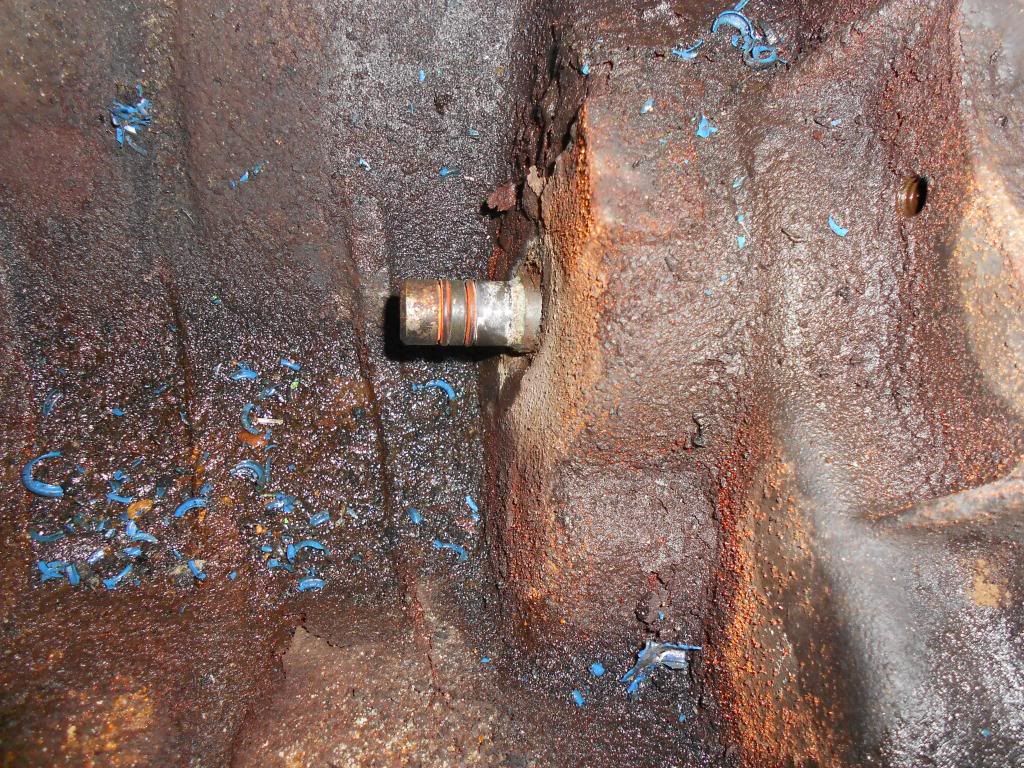
18.
Install the PI Water tube.
Another view:
Don't forget to reconnect the bonding wire. I moved my drivetrain grounding wire from the transmission case to the back of the head for easier accessibility.
19.
Reinstall the water pump. Don't forget the new O-ring. The old O-ring expands too much and you cannot reuse it. I also put a small bit of Blue RTV around the edge of it to prevent leaking. Temp install the pulley with 4 10mm bolts. Note: Powdercoated Satin Black bolts
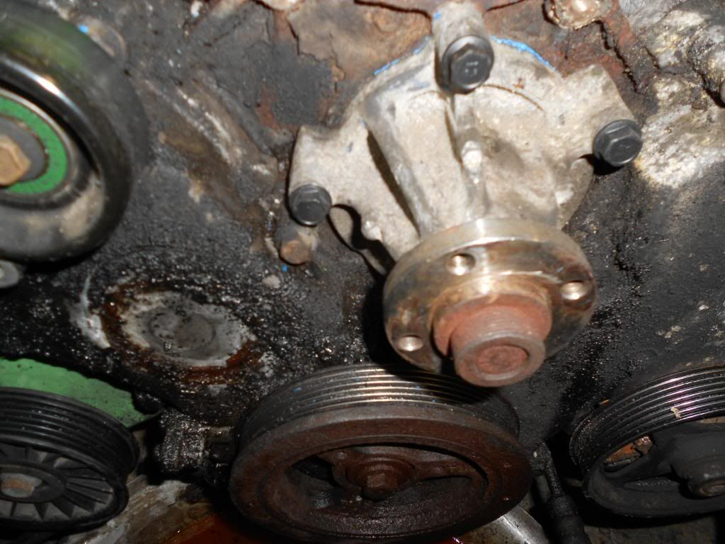
20.
Remove the old intake gaskets and clean up the mating surfaces. Put paper towels or rags in each cylinder to prevent Foreign Object Debris (FOD) from entering the cylinder. As I wall putting a paper towle into #1, a piece of old conduit went into the head. It's a good thing I have a sweet pair of loooong needle nose pliers.
21.
This is where it gets fun.
Set the PI Intake Manifold on the engine.
--*92-95*-- Now it's time to break apart the old stupid plastic wire loom. You can break it apart by hand, because after 20 years of use, it's quite brittle.
Lay out the wiring, and start making new wiring looms. Use plastic conduit and make the passenger side fuel injector harnesses.
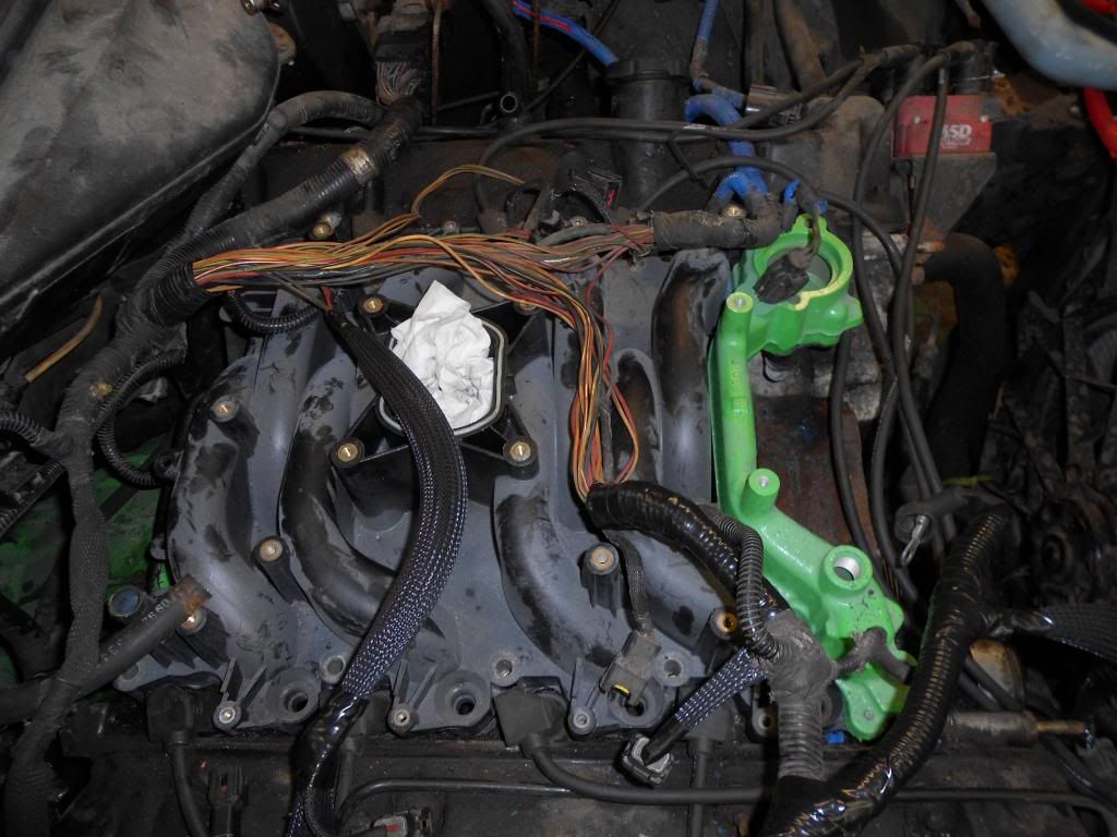
Also temporarilly install the alternator and the fuel injectors to make sure you have all the wiring in the correct order. I also temp installed the upper intake plenum to make sure the harness was going to fit underneath it.
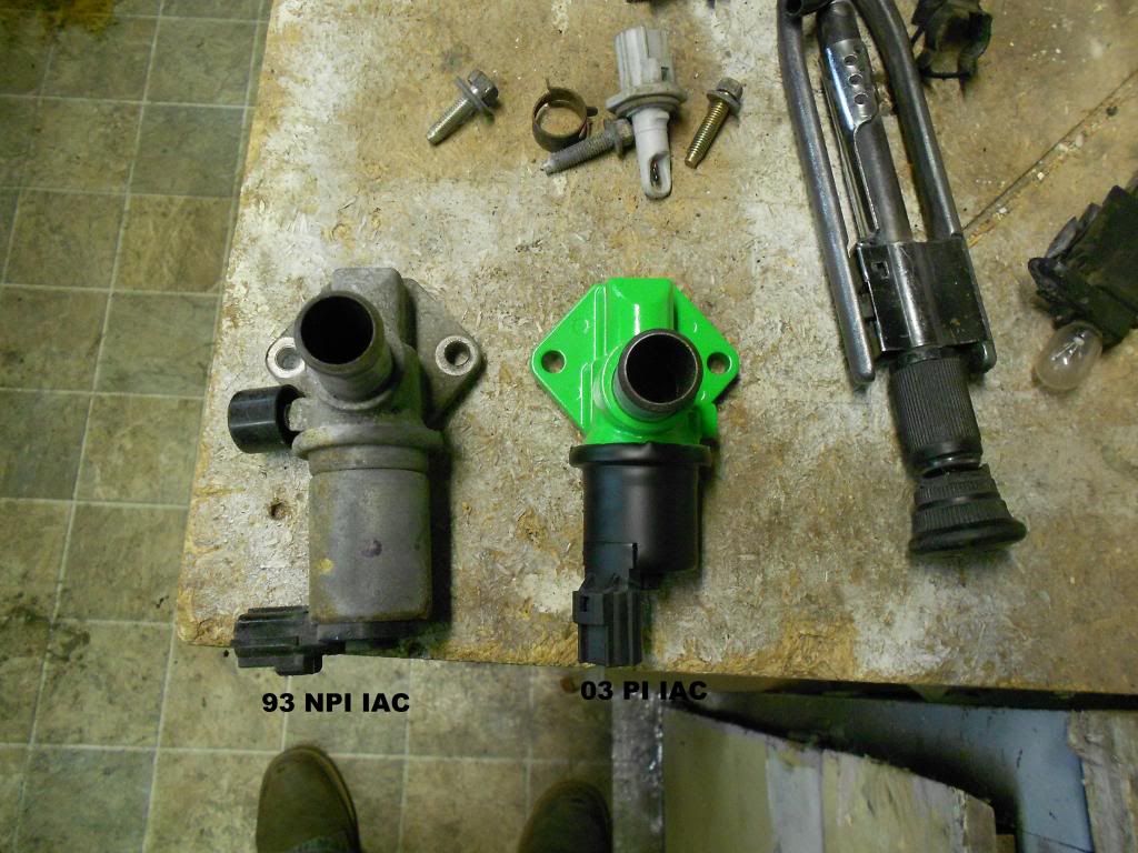
-92-95 Modify the IAC wiring:
--Because the IAC is relocated from underneath the manifold to the side of the upper plenum, the wiring has to be extended. You may reuse the old IAC, but I opted for a newer one, and to make mine a little more colorful.
There are only two wires to extened. Cut the two wires going to the IAC. Connenct the red wire from the harness to the red wire of the NEW connector. And connector the other wire, white/blue, to the other remaining wire; white/orange.
Here:
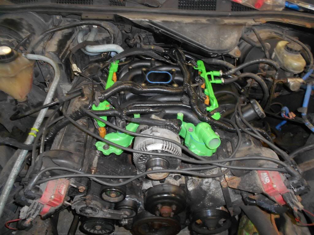
-92-95 Extend the DFPE wiring:
-- the DFPE sensor is moved from the back of the intake plenum to the throttle bracket on the upper plenum. I just cut, and extended the wiring about 10" and reused the original sensor and connector.
Here is the finished product. This should give you some idea on how it should look.
22.
Remove all of the temp installed items from the previous step (Alternator, upper plenum, injectors and PI Intake Manifold)
22.1
*92-95* Remove the 2 11mm nuts on the firewall for the throttle cable. Then, disconnect the throttle cable from the back of the gas pedal, and pop off the large metal clip above the gas pedal that holds the throttle cable.
Remove the entire throttle cable assembly.
22.2
*92-95* Install the new throttle cable. Mount it to the firewall with the 2 11mm nuts. Reconnect to the gas pedal and reinstall the large metal clip. Let the throttle cable lay in the inner fender area o nthe drivers side.
23.
Test fit the PI gaskets. I found that the dowels on the gaskets are opposite the holes on the NPI heads. Not even close.
So I carefully removed the alignment dowels from the gaskets with a Dremel. Then, set them down on the heads to ensure that they will sit flat and flush.
*** Put Blue RTV around the water jacekts on the gasket. They are slighty different and may leak if you do not put Blue RTV on it.***
24.
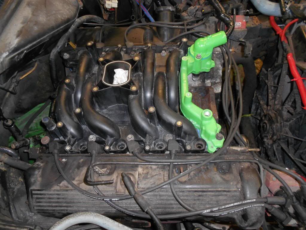
Install the PI intake Manifold. Then install the thermostat O-ring and thermostat, then install the thermostat housing.
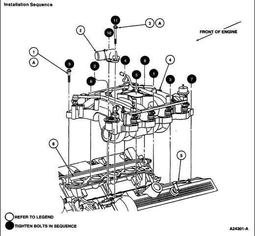
Torque all bolts inthe correct tightening sequence to 15-22ft/lbs.
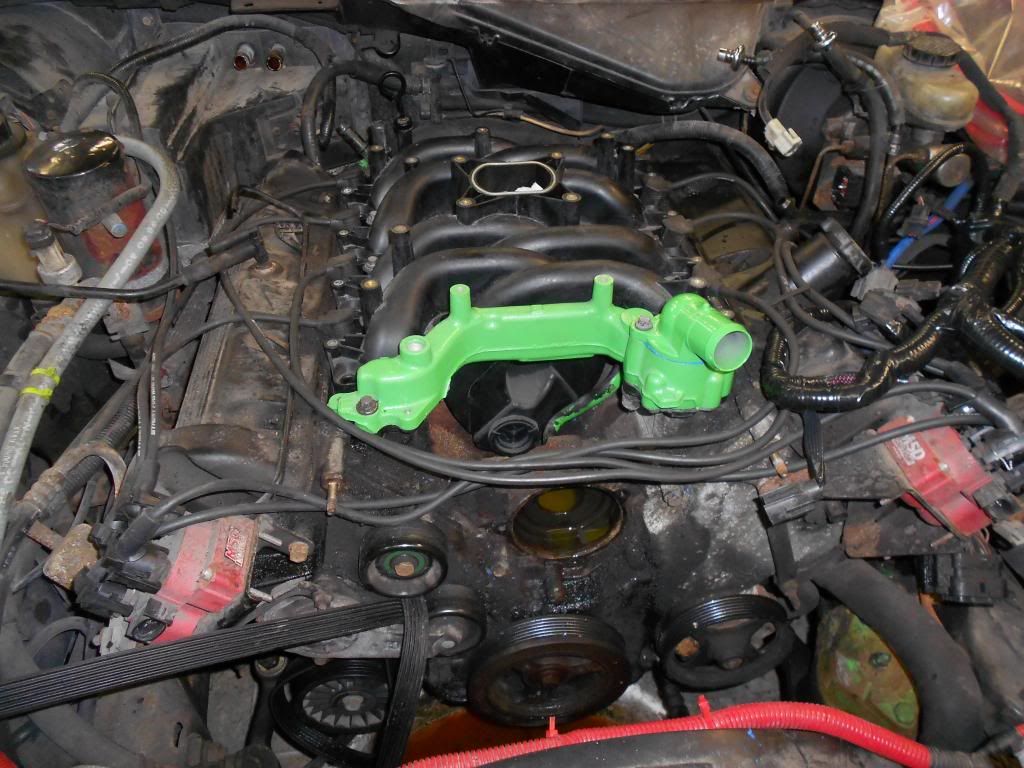
Another view:
TORQUE SEQUENCE
25.
Install new O-rings on the injectors and reinstall the injectors.
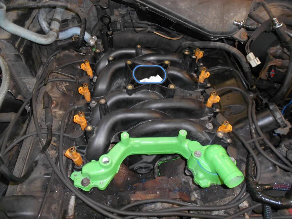
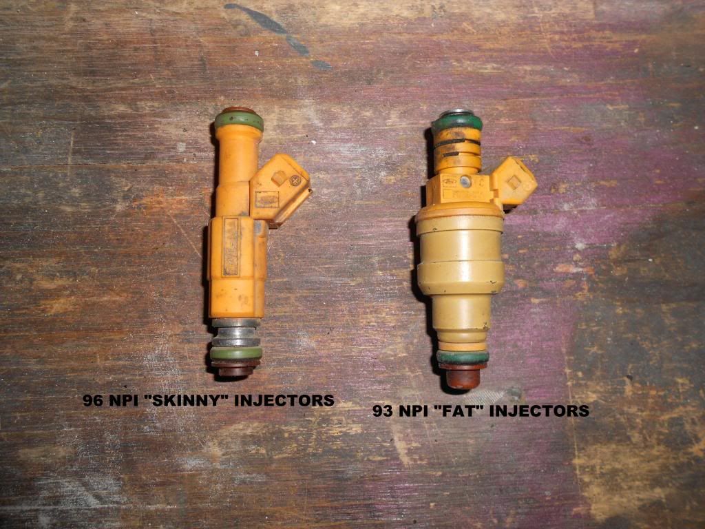
Note: I used the "skinny" injectors because I got a great deal on them. They hook right up to the harness.
Comparision:
26.
Install the new 96+ fuel rail. Install the 4 8mm bolts and reconnect the fuel lines.
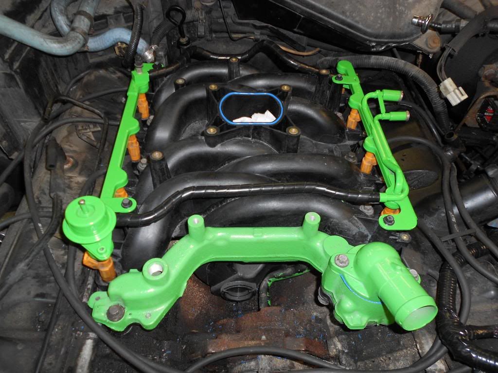
27.
Start reconnecting the engine harness.

28.
Reinstall the alternator and reconnect the alternator wiring.
28.1
Reinstall the accessory belt.
28.2
Reinstall the mechanical fan and the fan shroud.
28.3
Reconnect the radiator return line to the thermostat housing.
29.
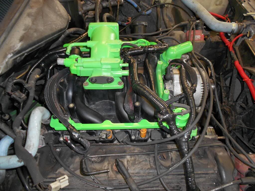
I installed the new IAC (with new gasket) and EGR block off plate(with new gasket) while the upper plenum was sitting on the bench.
-->The 92-95 Panthers require 6 vacuum lines,and the 96+ require 7 vacuum lines. I capped one vacuum line. Eventually, I will use that extra vacuum line as a pick up for the vaccum gauge.
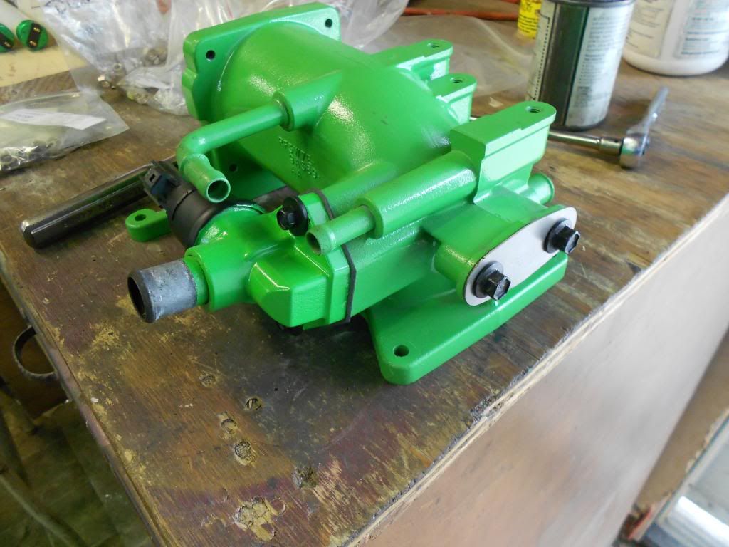
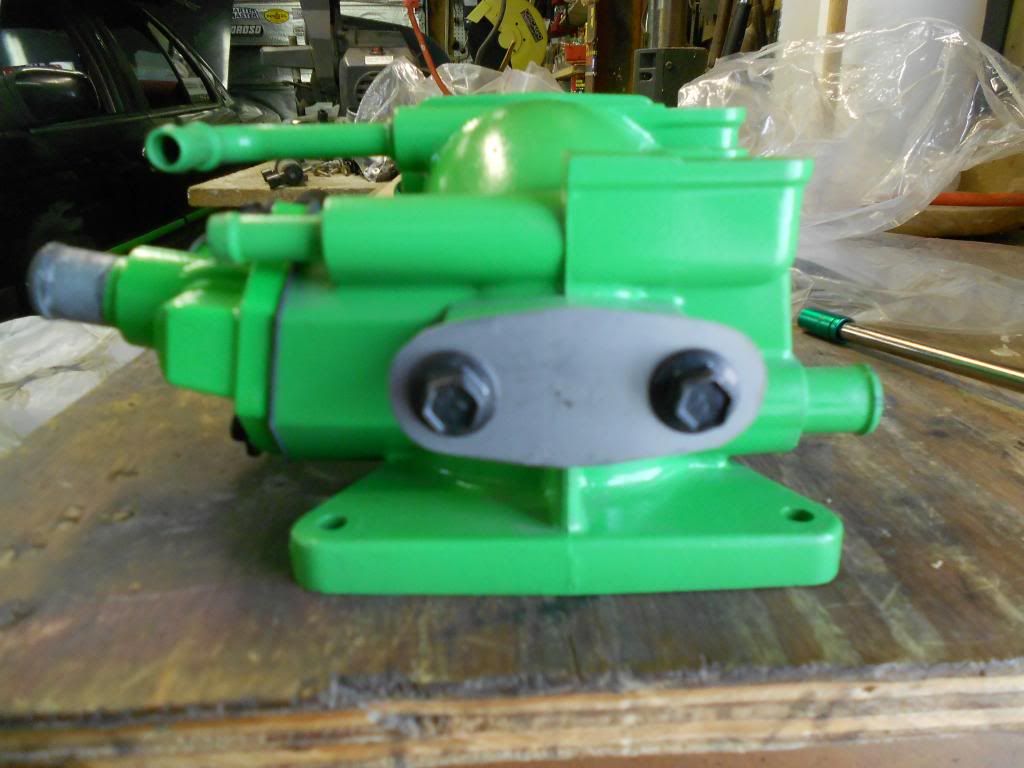
Then, install the upper plenum with 5 8mm bolts.
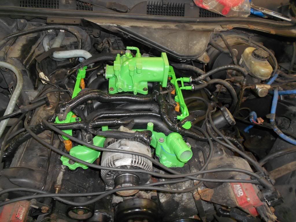
Another view:
30.
Install the throttle cable bracket with the DFPE sensor. Then connect all the vacuum lines to their applicable locations. The IAC and drivers side PCV can wait until the air intake is installed.
31.
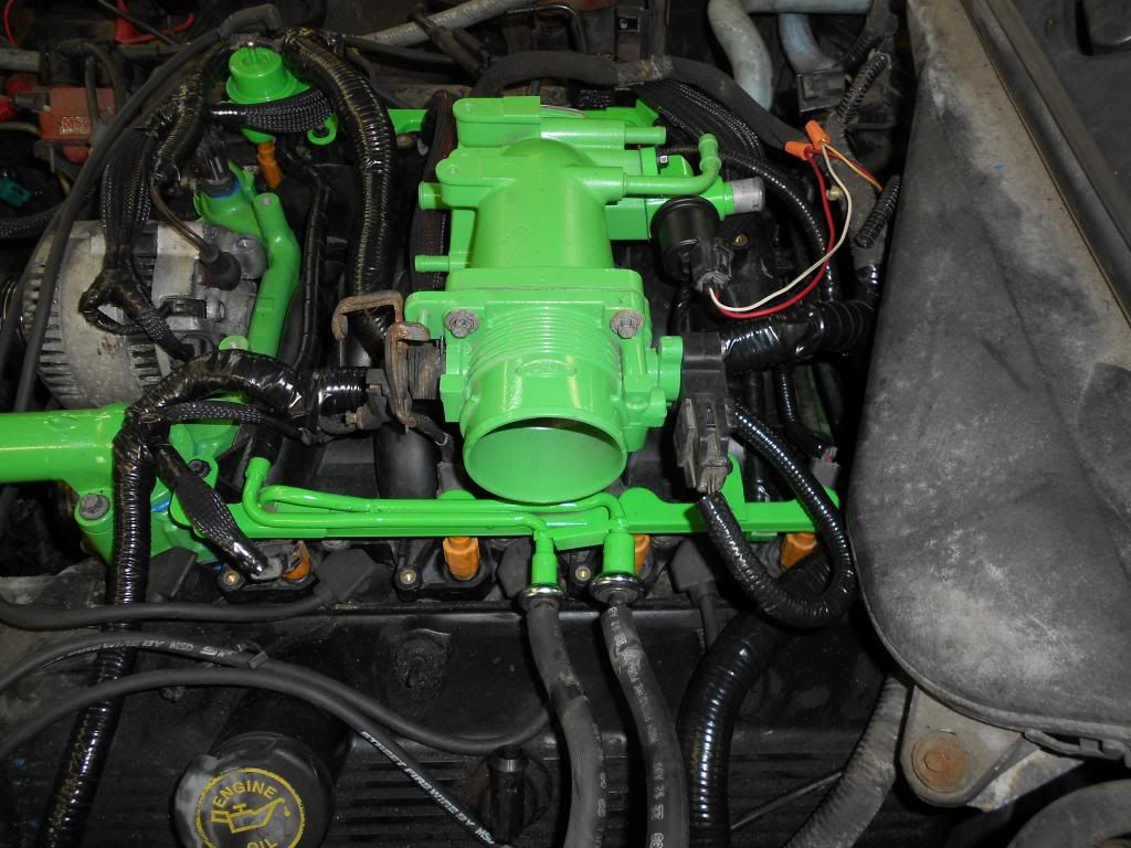
Install the throttle body, with a new gasket. You can reuse the old throttle body, but you have to swap out the linkage with a 96+ because the 92-95's pull from the the front of the throttle body, and the 96+ pull from the rear. Plus, the ends of the throttle cables are different. It's just much easier to get a 96+.
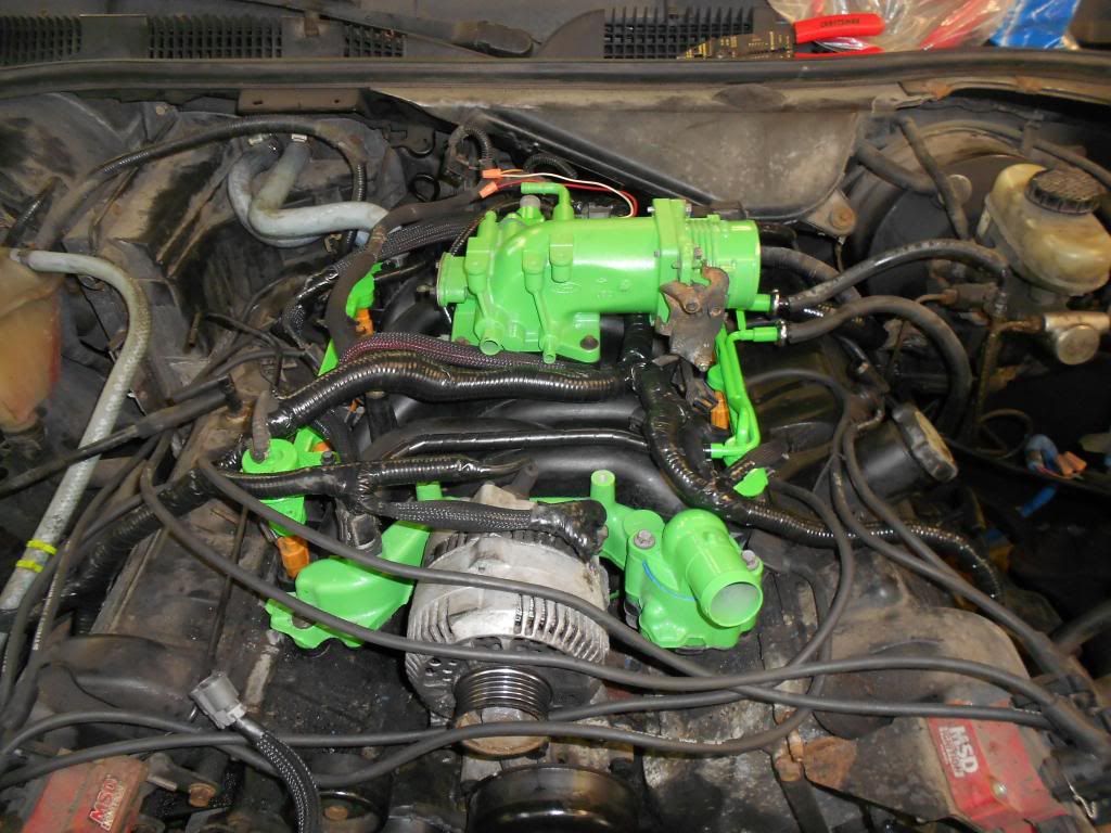
Facing the throttle body:
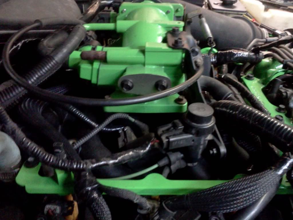
32.
Connect the new throttle cable. Do not forget to install the spring.
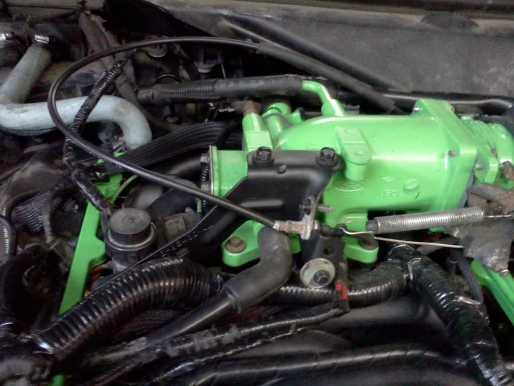
Side view:
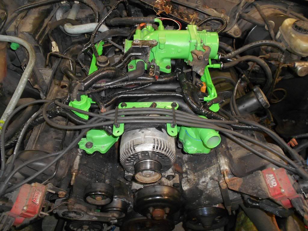
33.
Install the 96+ spark plug wire loom. Connect the spark plug wires to the loom, and install the bolts to secure the alternator.
34.
Install the air intake and hook up the required vacuum lines.
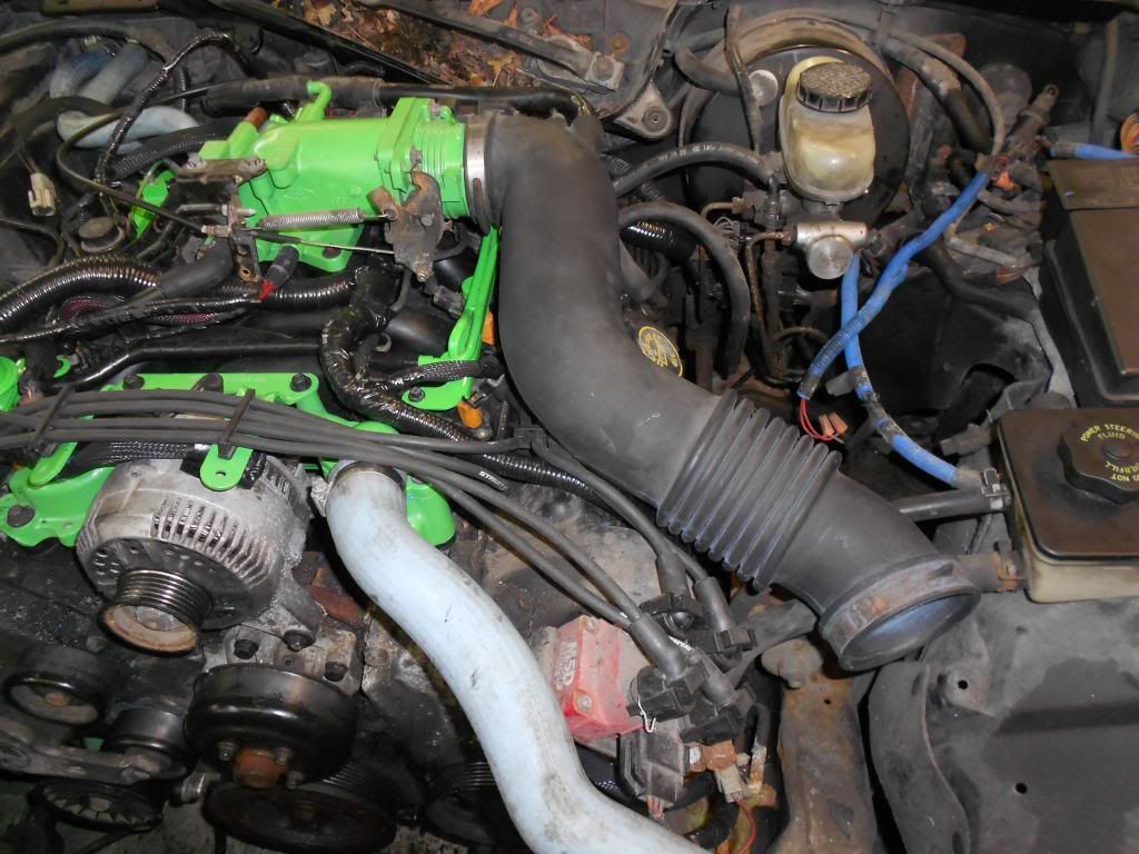
Vacuum lines:
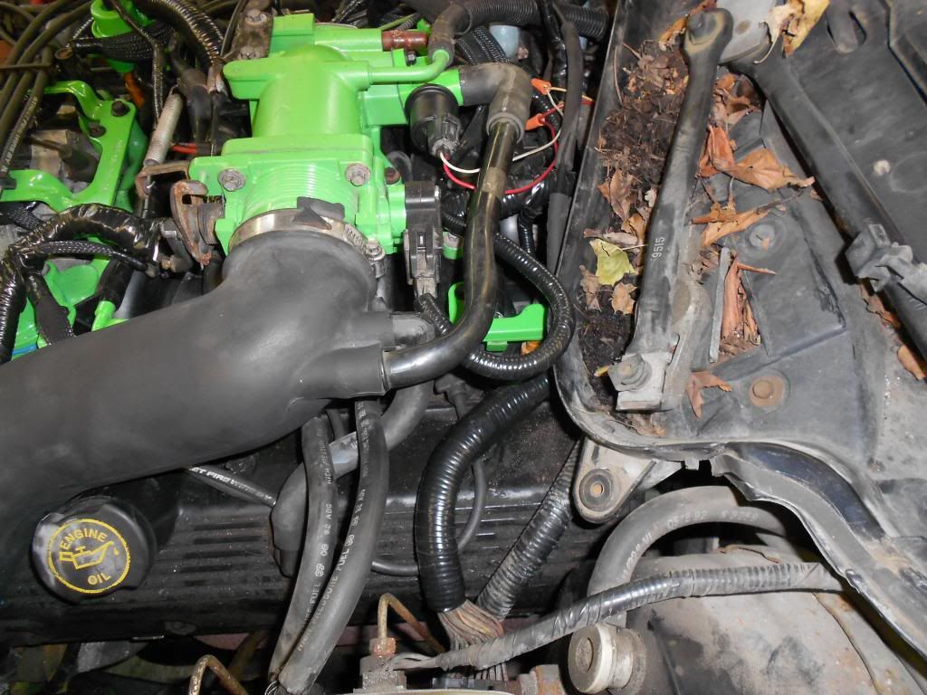
35.
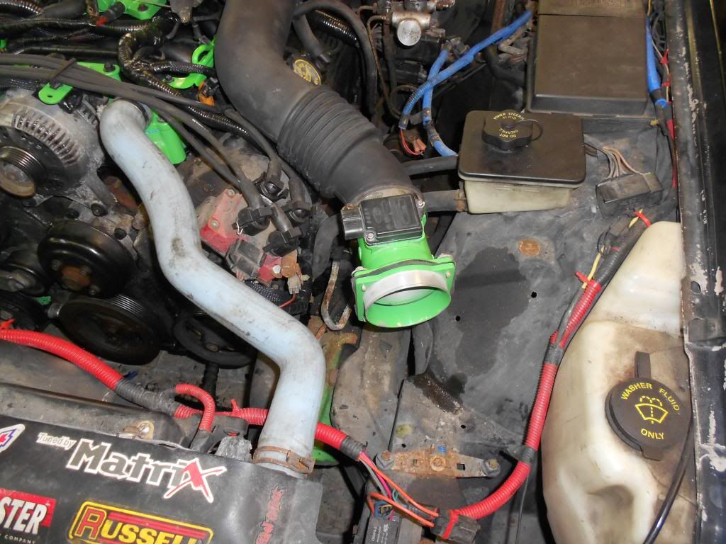
Install the MAF housing .
36.
Here's where it varies. I had an aluminum intake installed, and there was spot tapped out for the IAT sensor. Normally, they are located in the air box, which I do not have. I drilled out a hole in the air intake, and mounted the IAT there.
Also, I have a MAF adapter to mount a concial filter on the end of my air intake system.
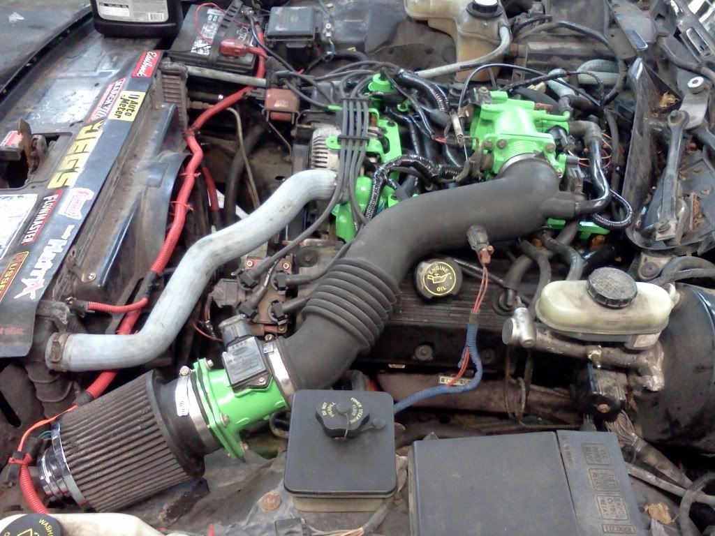
I had to use the filter from my old 1998 SVT Countour. It was the only one that would mount to the MAF adapter correctly.
37.
Start filling up the coolant reservoir.
38.
Reconnect the battery.
39.
Turn the key to the "ON" position a few times to cycle the fuel pump and build up pressure.
40.
Start your engine! Be on the look out for leaks and bad noises (you know exactly what I'm talking about). Don't let it run for too long, because there isn't enough coolant in it. It took me 4 tries to get the coolant level up to the correct levels.
41.
As long as there are no fluid or vacuum leaks, and the vehicle runs fine, time to take a test drive! You should notice a difference in the mid to upper RPM range.
42.
Win. Crack open a celebratory* beer and enjoy the success!
During this time, there are many options available. Upgrading water pumps, fuel injectors, upper plenums, throttle bodies, intakes, spark plugs and wires and so forth.
I did this swap because I had a blown intake manifol gasket, and because I'm planning on swapping in PI heads/engine soon. This intake swap would allow me to simply disconnect everything and go about the engine install. This way, if something goes wrong with the engine install, I can locate the problem easier.
-ryan s.
This write involves everything that entails installing a Perfomance Improved (PI) Intake Manifold on a Non-Performance Improved (NPI) engine.
First, this write up is aimed at the 92-95 NPI engines.
Secondly, this swap will be much easier for the 96+ crowd. Mainly, because you do not have to modify the engine harness.
To start things off, here is a list of parts you will need. All the items that are bold are REQUIRED for both 92-95 and 96+ systems.
Parts List:
- PI Intake Manifold (any PI will work; I used a FRPP unit from a 04 Mustang GT)
- PI Intake Manifold Gaskets(kit includes upper plenum gasket)
- Upper Intake Plenum
- Throttle body
- Idle Air Control (IAC) Valve
- Air Intake
- 96-97 Fuel Rail
- PI Heater Core Return Line
- PI Water Pump Inlet Nipple
- 96-97 Spark Plug Wire Bracket
- Water Pump O-ring
- IAC Gasket
- Throttle Body Gasket
- Thermostat Housing O-Ring
- 96+ Throttle Cable
- 96+ Throttle Cable Bracket with spring
- Fuel Injectors (Skinny)
- Fuel Injector O-Rings (16)
- 96+ vacuum lines. All of them.
- Save as much harware from the junkyard as possible.
Consumables:
- Blue RTV
- 1 gallon of coolant. I use the straight glycol and mix it myself. I see 50/50 as a waste of money.
- Brake cleaner
- Paper towels
- Beer
Specialty Tools:
- Fuel rail disconnect kit
- Mechanical fan removal kit- I forgot that most people have this still installed.
This will take a while. So don't plan on having your car for a solid weekend. It will not take 4 hours. It may take your less or more time depending on your mechanical ability and how much other maintenance you would like to get done while you have parts off your car.
1.
Find a suitible vehicle to do the swap!

2.
You don't have to do this, but I removed the hood for A. more light B. less hitting my head and C. more room.

3.
Disconnect the battery. (Another option. I removed the battery because I needed to install and new one.)

4.
Put a suitable containter under the radiator on the drivers side. Open the petcock and start to drain the coolant.
5.
Disconnect the Intake Air Temperature (IAT) Sensor and the Mass Air Flow (MAF) Sensor and remove the air intake.

6.
Pop off the throttle cable with a flat screwdriver, and remove the 4 8mm bolts to remove the throttle body. Set the throttle cable to side on the drivers side inner fender area.

7.
By now, there should be enough coolant drained to reposition the radiator return line. To keep the mess down, I loosened the clamp from the thermostat housing, the loosened the clamp on the radiator and rotated the hose over to the power steering reservoir. The same applies to the coolant line that goes to the heater core from the intake manifold. Disconnect it from the manifold and rotate it upwards to keep the mess down. (I remove and replaced mine with CVPI silicone hoses)
7.1
I realize that not every car has the mechanical fan removed like the Tank. Use the mechnical fan removal tool(s), loosen the fan. Remove the 4? bolts that hold in the fan shroud. Then remove the shroud and fan assembly.
8.
IMPORTANT!- use a ratchet or an impact ratchet and loosen the 4 10mm bolts on the water pump pulley. DO NOT REMOVE THE PULLEY UNTIL THE BELT HAS BEEN REMOVED!

9.
Disconnect all the sensors and start to remove the engine harness. On the drivers side, underneath, you do not have to disconnect the Oil Pressure Sensor or the Power Steering Pump Speed Valve Sensor. They may remained connected.
Start on the passenger side. Underneath, disconnect the Crank Position Sensor (CPS) and the Air Conditioning Clutch plug. Then, disconnect the Alternator Charge cable to the Distribution Box. Disconnect the coil pack, emissions, fuel injector wiring( 92-95- Label each injectors position. Wrap a slice of duct tape on it and write # 1-8 on each connector for it's coresponding cylinder number. The engine harness needs to be broken free of the stupid plastic piece that holds it all together on top of the intake manifold. You don't want to spend time trying to figure out which injector harness goes where), alternator wires, and coolant sensor to the harness.
9.1
-92-95 Disconnect the vacuum line to the intake plenum. then remove the braket on the backside (2 8mm bolts)<--8mm ratcheting wrench will save you]. Then remove the 4 8mm bolts and remove the intake plenum assembly.
Then make your way disconnecting everything around the back of the motor. the O2 Sensors are hooked up to the engine harness, so they may be a bit difficult to get to. Step 9.1 makes this easier for the 92-95.
Remove the connection to the IAC, Throttle Position Sensor (TPS), Exhaust Gas Recirculate (EGR) Valve and sensor. Then the drivers side fuel injectors, coil pack, camshaft sesnor, and coolant sensor. Lastly, disconnect the engine harness from the connection that goes to the Powertrain Control Mondule (PCM). It's located unter the brake master cylinder and requires the loosening of one 10mm bolt. Then carefully removed the connector and lay the entire harness on the drivers side fender/area.
Also, remove the vacuum lines as well during this time.
10.
Use a 1/2" drive breaker bar (or equivilant) and relieve pressure on the tensioner and remove the accessory belt. Replace if necessary.
11.
Remove the 3 8mm bolts and the 2 10mm bolts, then remove the alternator.
12.
By now, the coolant should be mostly drained via the petcock. Close the petcock, and move the container under the water pump. Remove the loosened 4 10mm bolts, remove the pulley, then remove the 5 13mm bolts that hold the water pump, and remove the water pump.
13.
Using the fuel line disconnect tool, disconnect the two fittings that connect to the fuel rail. Take a small piece of mechanics wire/saftey wire/zip tie/string and tie the to the cap on the brake reservoir. This will keep them out of the way, and spilling gasoline and making more of a mess.
Remove the 4 8mm bolts and remove the fuel rail and the injectors.
--edit image-----

14.
Remove the 11 10mm bolts that hold the intake to the heads. Although it is aluminum, it weighes roughly 30 lbs, so be prepared for it, especially because Panthers are so wide.
I kept the bolts in order for reinstalltion.

Intake removed:

Another look, showing the Heater Core Return Line that needs to be replaced/put out of its misery.

And the blown out intake manifold gasket on the drivers side. This is the whole reason this swap is going on.

15.
THIS APPLIES TO ALL VEHICLES
Disconnect the bonding wire from the back of the engine and remove the old Heater Core Return line.
The return line has to be changed out because the PI Intake manifold is so big, that the line interferes with the manifold laying flush. The line and the nipple that it connects to on the back of the water pump must be replaced with a PI version.

16.
Using a ball peen hammer, gently tap out the old nipple on the back the water pump.

17.
Use a deep well socket (I used an 11mm. It worked out that way) and tap the new nipple into place. I put a small amount of Blue RTV around the lip of the nipple where it mates to the block to prevent any leaking.

Newly installed.

18.
Install the PI Water tube.

Another view:

Don't forget to reconnect the bonding wire. I moved my drivetrain grounding wire from the transmission case to the back of the head for easier accessibility.

19.
Reinstall the water pump. Don't forget the new O-ring. The old O-ring expands too much and you cannot reuse it. I also put a small bit of Blue RTV around the edge of it to prevent leaking. Temp install the pulley with 4 10mm bolts. Note: Powdercoated Satin Black bolts


20.
Remove the old intake gaskets and clean up the mating surfaces. Put paper towels or rags in each cylinder to prevent Foreign Object Debris (FOD) from entering the cylinder. As I wall putting a paper towle into #1, a piece of old conduit went into the head. It's a good thing I have a sweet pair of loooong needle nose pliers.
21.
This is where it gets fun.
Set the PI Intake Manifold on the engine.
--*92-95*-- Now it's time to break apart the old stupid plastic wire loom. You can break it apart by hand, because after 20 years of use, it's quite brittle.
Lay out the wiring, and start making new wiring looms. Use plastic conduit and make the passenger side fuel injector harnesses.

Also temporarilly install the alternator and the fuel injectors to make sure you have all the wiring in the correct order. I also temp installed the upper intake plenum to make sure the harness was going to fit underneath it.
-92-95 Modify the IAC wiring:
--Because the IAC is relocated from underneath the manifold to the side of the upper plenum, the wiring has to be extended. You may reuse the old IAC, but I opted for a newer one, and to make mine a little more colorful.
There are only two wires to extened. Cut the two wires going to the IAC. Connenct the red wire from the harness to the red wire of the NEW connector. And connector the other wire, white/blue, to the other remaining wire; white/orange.
Here:

-92-95 Extend the DFPE wiring:
-- the DFPE sensor is moved from the back of the intake plenum to the throttle bracket on the upper plenum. I just cut, and extended the wiring about 10" and reused the original sensor and connector.
Here is the finished product. This should give you some idea on how it should look.

22.
Remove all of the temp installed items from the previous step (Alternator, upper plenum, injectors and PI Intake Manifold)
22.1
*92-95* Remove the 2 11mm nuts on the firewall for the throttle cable. Then, disconnect the throttle cable from the back of the gas pedal, and pop off the large metal clip above the gas pedal that holds the throttle cable.
Remove the entire throttle cable assembly.
22.2
*92-95* Install the new throttle cable. Mount it to the firewall with the 2 11mm nuts. Reconnect to the gas pedal and reinstall the large metal clip. Let the throttle cable lay in the inner fender area o nthe drivers side.
23.
Test fit the PI gaskets. I found that the dowels on the gaskets are opposite the holes on the NPI heads. Not even close.
So I carefully removed the alignment dowels from the gaskets with a Dremel. Then, set them down on the heads to ensure that they will sit flat and flush.
*** Put Blue RTV around the water jacekts on the gasket. They are slighty different and may leak if you do not put Blue RTV on it.***
24.
Install the PI intake Manifold. Then install the thermostat O-ring and thermostat, then install the thermostat housing.
Torque all bolts inthe correct tightening sequence to 15-22ft/lbs.

Another view:

TORQUE SEQUENCE

25.
Install new O-rings on the injectors and reinstall the injectors.

Note: I used the "skinny" injectors because I got a great deal on them. They hook right up to the harness.
Comparision:

26.
Install the new 96+ fuel rail. Install the 4 8mm bolts and reconnect the fuel lines.

27.
Start reconnecting the engine harness.

28.
Reinstall the alternator and reconnect the alternator wiring.
28.1
Reinstall the accessory belt.
28.2
Reinstall the mechanical fan and the fan shroud.
28.3
Reconnect the radiator return line to the thermostat housing.
29.
I installed the new IAC (with new gasket) and EGR block off plate(with new gasket) while the upper plenum was sitting on the bench.
-->The 92-95 Panthers require 6 vacuum lines,and the 96+ require 7 vacuum lines. I capped one vacuum line. Eventually, I will use that extra vacuum line as a pick up for the vaccum gauge.


Then, install the upper plenum with 5 8mm bolts.

Another view:

30.
Install the throttle cable bracket with the DFPE sensor. Then connect all the vacuum lines to their applicable locations. The IAC and drivers side PCV can wait until the air intake is installed.
31.
Install the throttle body, with a new gasket. You can reuse the old throttle body, but you have to swap out the linkage with a 96+ because the 92-95's pull from the the front of the throttle body, and the 96+ pull from the rear. Plus, the ends of the throttle cables are different. It's just much easier to get a 96+.

Facing the throttle body:

32.
Connect the new throttle cable. Do not forget to install the spring.

Side view:

33.
Install the 96+ spark plug wire loom. Connect the spark plug wires to the loom, and install the bolts to secure the alternator.

34.
Install the air intake and hook up the required vacuum lines.

Vacuum lines:

35.
Install the MAF housing .

36.
Here's where it varies. I had an aluminum intake installed, and there was spot tapped out for the IAT sensor. Normally, they are located in the air box, which I do not have. I drilled out a hole in the air intake, and mounted the IAT there.
Also, I have a MAF adapter to mount a concial filter on the end of my air intake system.

I had to use the filter from my old 1998 SVT Countour. It was the only one that would mount to the MAF adapter correctly.
37.
Start filling up the coolant reservoir.
38.
Reconnect the battery.
39.
Turn the key to the "ON" position a few times to cycle the fuel pump and build up pressure.
40.
Start your engine! Be on the look out for leaks and bad noises (you know exactly what I'm talking about). Don't let it run for too long, because there isn't enough coolant in it. It took me 4 tries to get the coolant level up to the correct levels.
41.
As long as there are no fluid or vacuum leaks, and the vehicle runs fine, time to take a test drive! You should notice a difference in the mid to upper RPM range.
42.
Win. Crack open a celebratory* beer and enjoy the success!
During this time, there are many options available. Upgrading water pumps, fuel injectors, upper plenums, throttle bodies, intakes, spark plugs and wires and so forth.
I did this swap because I had a blown intake manifol gasket, and because I'm planning on swapping in PI heads/engine soon. This intake swap would allow me to simply disconnect everything and go about the engine install. This way, if something goes wrong with the engine install, I can locate the problem easier.
-ryan s.



Comment